Battery Tray Repair

My battery tray had been ignored until I started messing around at the rear end and started removing the layers of flaking rust I found sitting back there. I thought about patching the holes but for the sake of £25 I'd replace the panel.

After a trip to Bug Jam I picked up a Creative Engineering replacement panel and started hacking the old battery tray out. Starting with a cutting disk close to the edge.
I then peeled away the spot welded edge and butchered the corner of the battery tray out with a pair of pliers, the way the Pros do it I'm told.

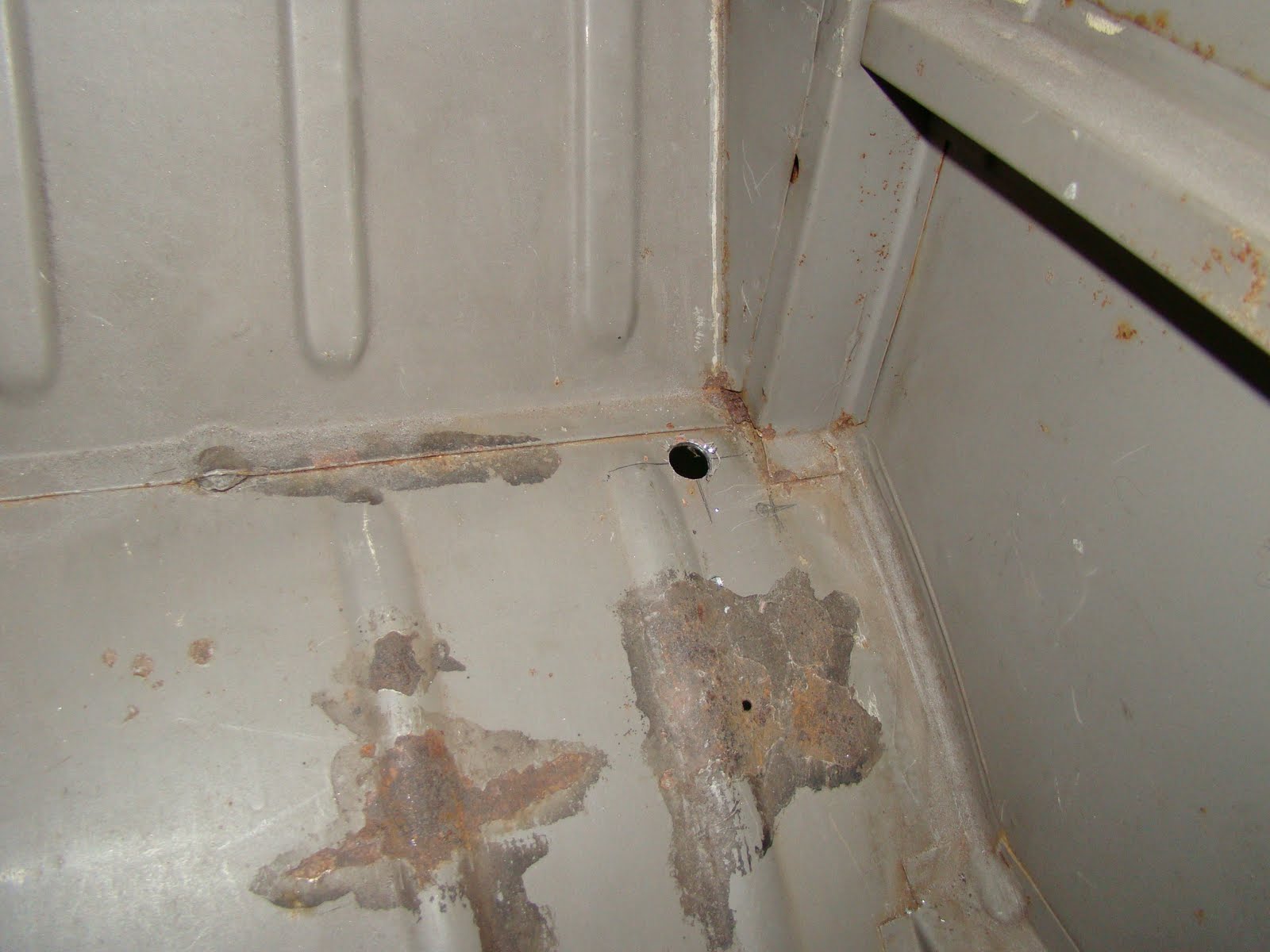
Cleaned up the underseal to discover the corrosion, the wobbly marker pen around the edge of the rust and holes gives you a better picture of the corrosion that needs removing.


 I cut away the marked out area and drilled off the spot welds on the corner fold to assess the rust underneath and cleaned away any lifted paint on the outside of the corner panel. I think I'm quite lucky with how little corrosion there is to my corners, although sometimes its easier to replace a whole panel than spend time patching up holes. 
A bargain Cosco sandblaster was used to clear out the pitting under the lip and to cover me and the rest of the garage in sand and grit.
 After reassessing the pitting to the outer skin of the corner panel I decided to just get rid of all the corrosion inside and out.

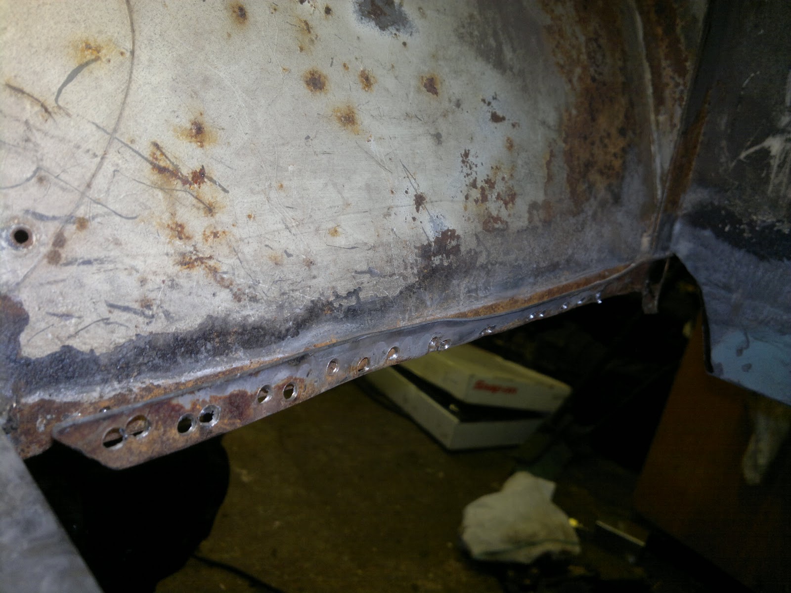
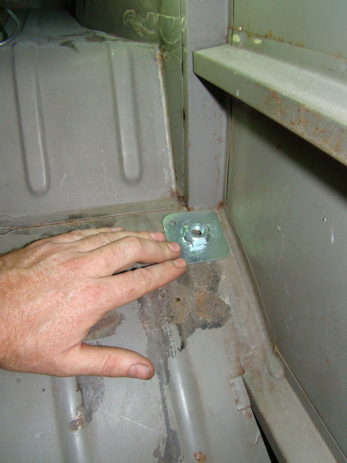
 The awkward part of this panel is that the battery tray panel is sandwiched between the rear wheel tub and the lower splash panel
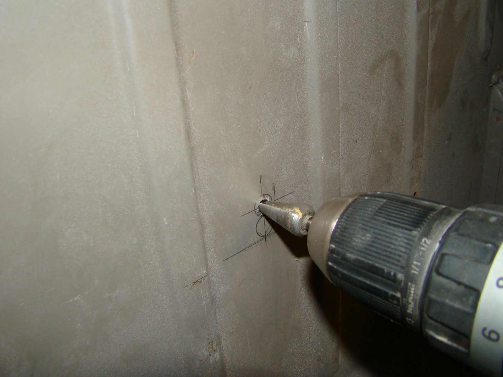
So with some delicate work with a drill I removed the spot welds on the splash panel and the battery tray lip that was fitted between the two, and tried to keep the wheel tub in as good condition as I could.
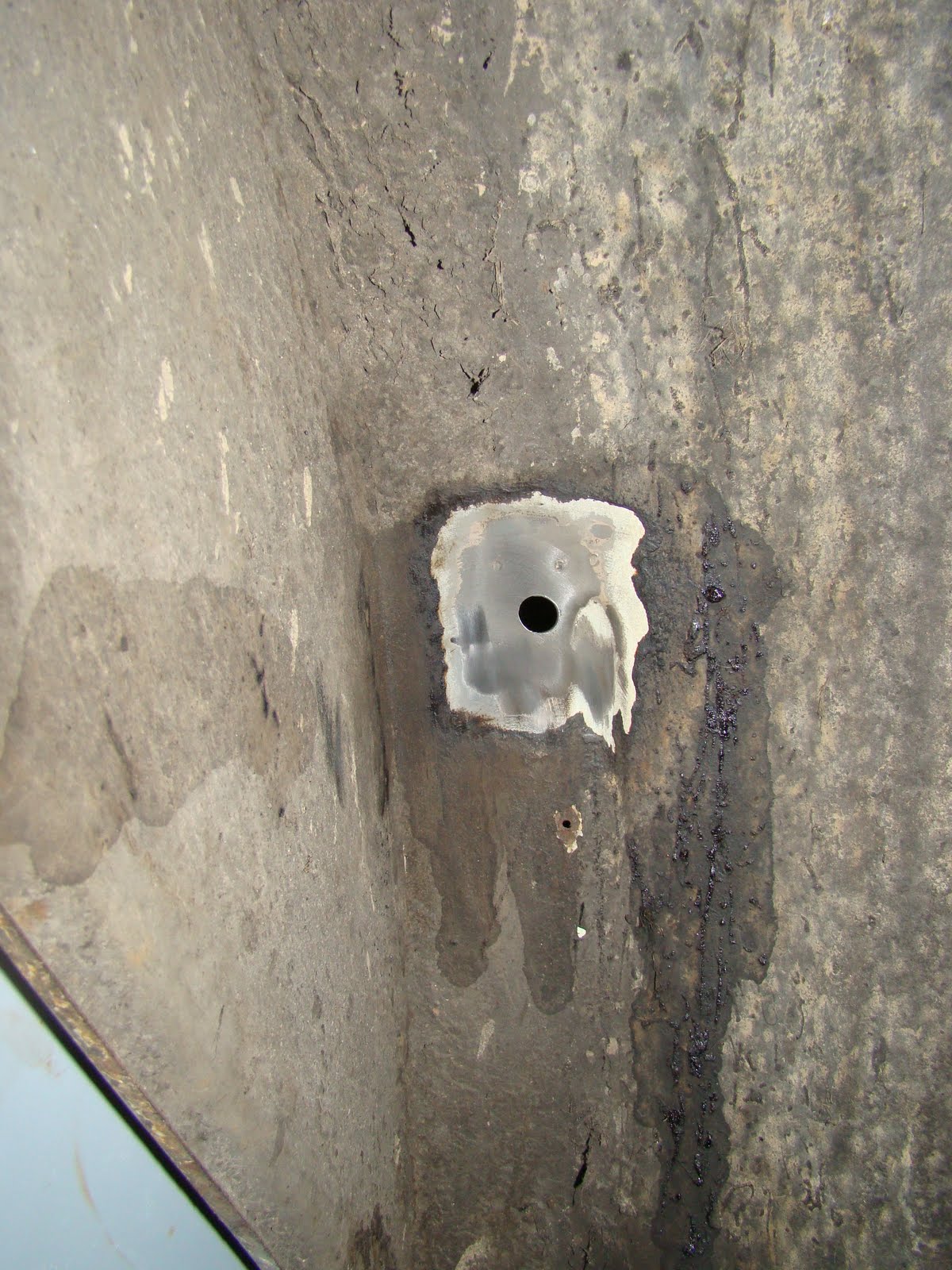
With the splash panel removed I stuck it in the sand blaster for a clean up, then welded up the spot weld holes. You may be able to see a strip of copper I used to stop the weld penetrating too far through the panel and also as a heat sink.
I replaced the corner that I left attached to the van when I ripped the panel out, using a piece I joggled and bent to fit.
A few hours' work and the splash panel is ready to fit back in.
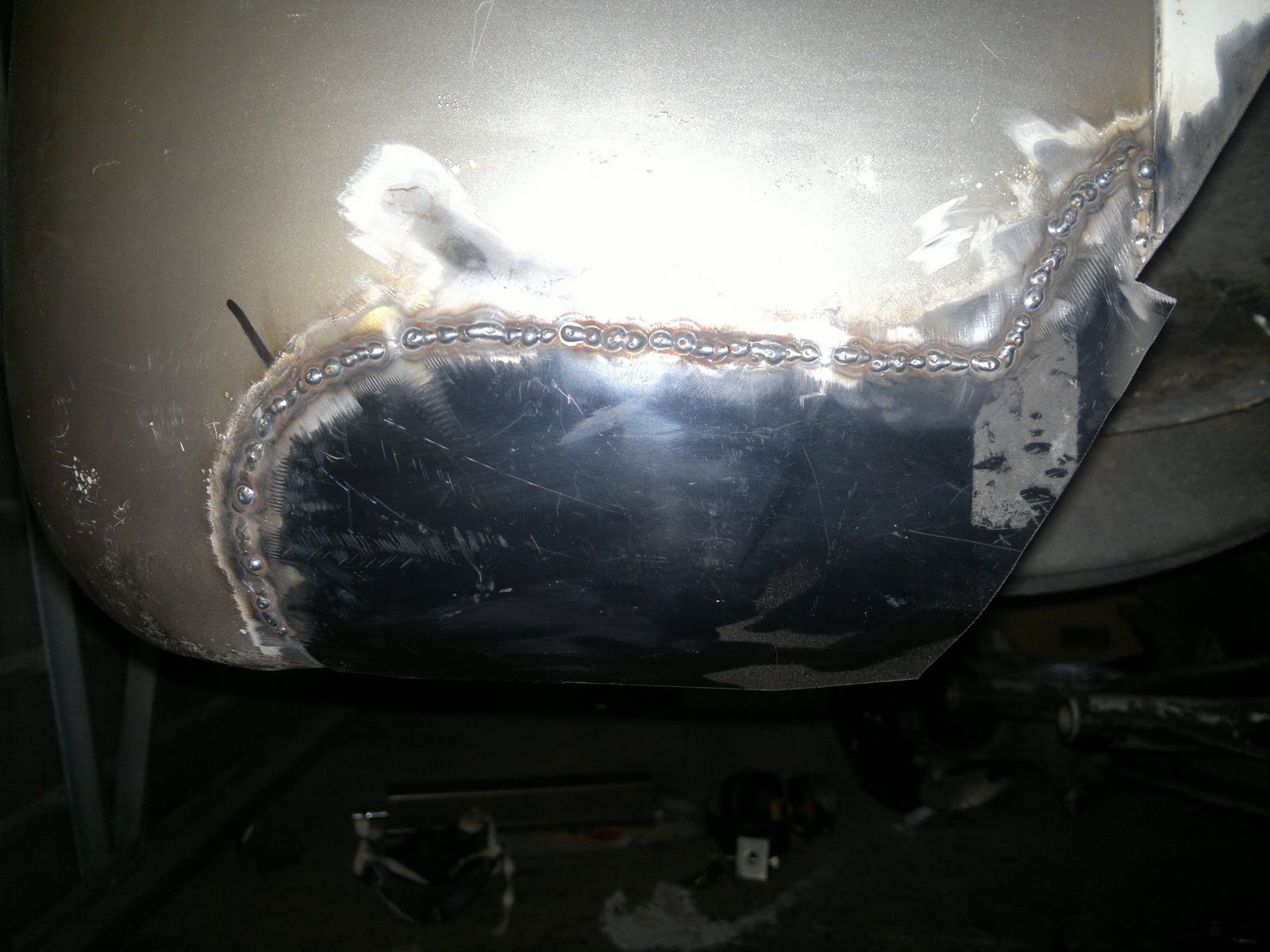
I then had the task of patching the double curved lower corner panel. This repair piece is cut from a cheap patch panel although it did not fit very well in its original shape I was able to position the panel to cut out a profile that closely matched what I needed for my repair patch.
A few tacks to ensure I kept the correct curve
I then very gingerly tacked the rest of the panel on. I ground off any welds that didn't penetrate enough and used a strong light behind the panel to find any gaps I'd missed once I had ground the welds flush. My method of taking it slowly to keep the panel from distorting was to only weld where the panel had cooled enough to touch, yes just like that bit in Men In Black. 
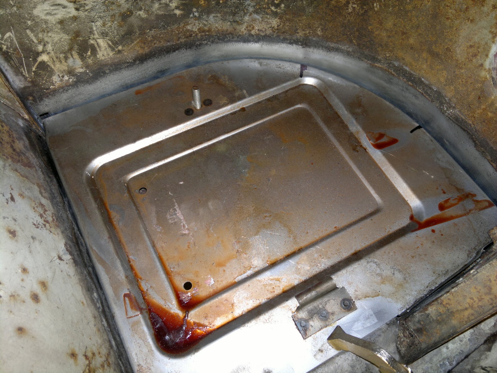
So a trial fit of the new battery tray panel from Creative Engineering didn't look too bad. The orange stuff on the panel is corrosion inhibitor not Hot Wing juice by the way. It can take me a while to get round to some jobs so best to keep the panels as fresh as possible.
The curved profile wasn't an exact match with about a 2-4 mm gap at either end, so I marked the contact points and beat the lip out on the edges and in on the crown of the curve, this didn't get it perfect but enough to get a better fit for panel beating later. 
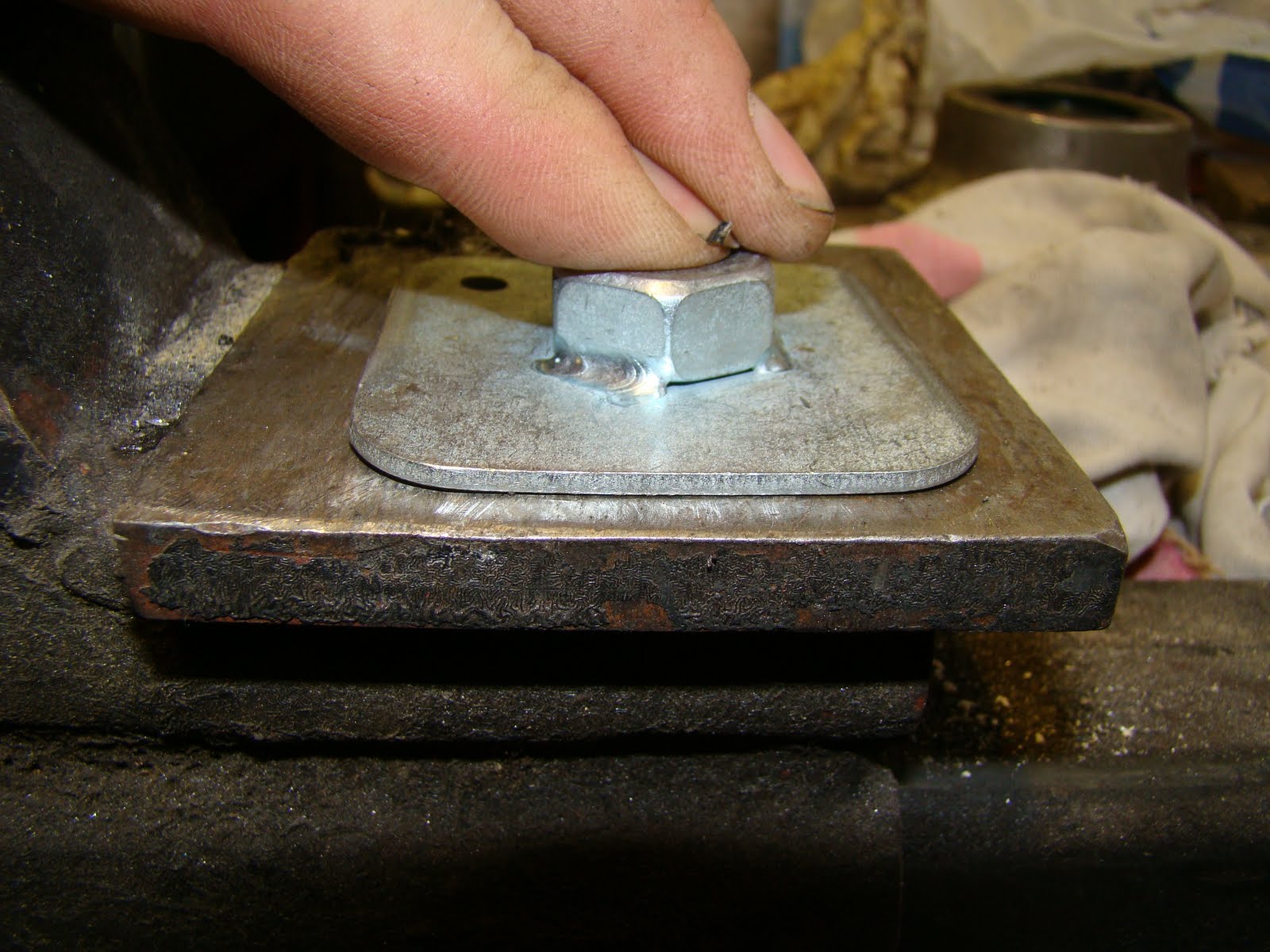
With a bit more messing around I finally got the panel in a position I was happy with. I used the joggled edge of the engine bay valance panel as my datum point for the corner of battery tray, (lower edge of picture) clamped the panel tight, then tacked the edge ready for a few spot welds.
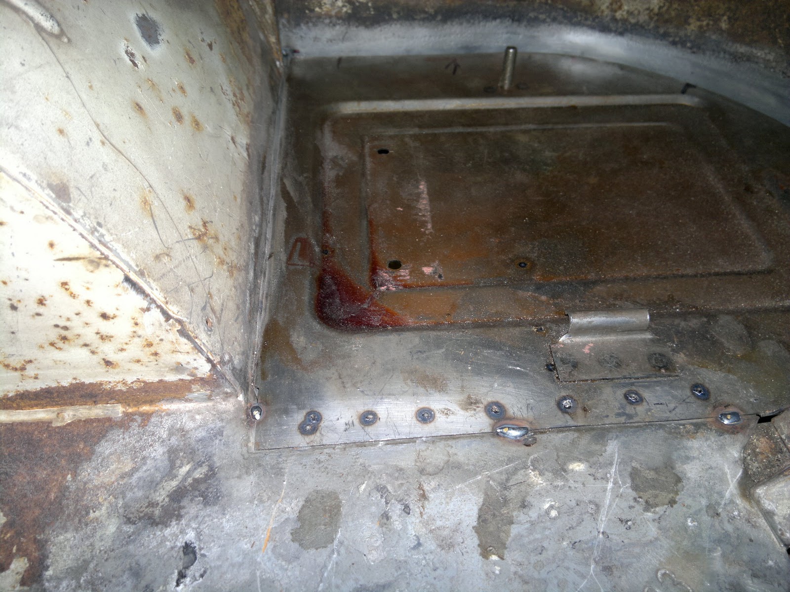
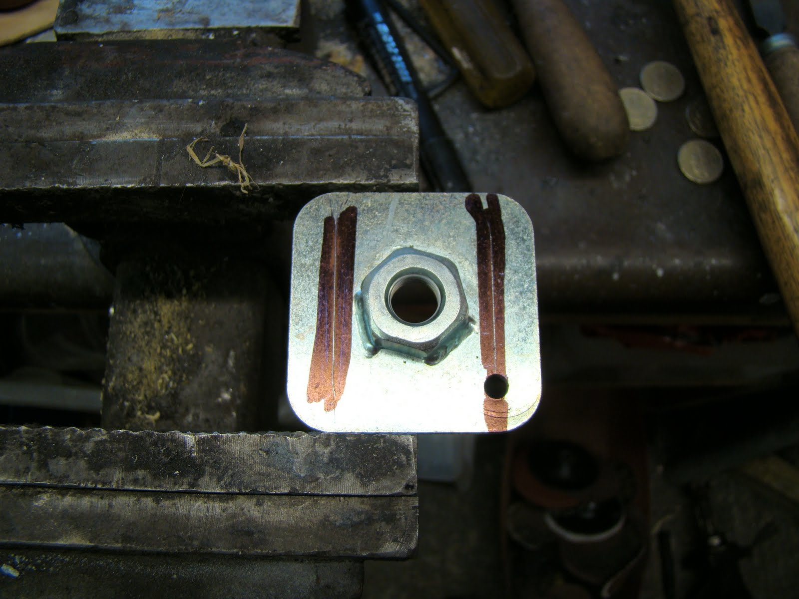
I then attempted to slide the splash panel back up between the two panels and spot weld the three panels together. It went a bit wrong. I realise now that I'd painted the edge of the panel with weld through primer and this didn't work well with the spot welder. I managed to get a couple of strong spot welds but the rest of the panel was MiG welded at the edges and where I burnt through the panel with the spot welder.

Front beam chassis repair


After taking the front beam off I ground out all the rust hiding under the beams upright. Here are a few pics of the repair patch.

Fitting Shocks to 4" Narrow Front Beam

I was able to have the privilege of using my Uncles old school belt driven lathe. It took me a couple of hours to get set up and remember how to use one of these from my apprenticeship days.
After 3 hours of messing about I finally produced these 12mm aluminium spacers. Trouble is they slid into the rubber bush more that I had measured for which sat the body of the shock just 2mm away from the upright of the beam.
I also calculated that the off set to the lower trailing arm mount to the the top mount is 35mm and I'd need to take the shoulder of the lower mount out by 12mm to keep the shock sitting vertically.
Or I could buy thinner Spax shock with swivel ends similar to what I have fitted to the back IRS.

Fitting Seat Belt Anchor Points

One of the many smaller jobs listed on the TO DO sheet once the van was back together was working out how to fit seat belts. There is a good thread on the SSVC forum about bus safety that I keep an eye on and this is where I've got most of my ideas from on how to fit seat belt mounting points to my van 
I picked this lot up from EuropaSpares.com - £1 for the plates and £1.29 for the bolts, a fair price considering the price some VW websites charge.
I started at the back, positioned the plate, marked it out then realised I need to fit my interior panels here somewhere as well.
So draging out my 1990 velour covered interior panel I started again
Here's the hole position from the inside. There will be one each side.
And where it is positioned from inside the wheel arch
I put a slight bend on the edge of the plates to fit the curve of the wheel arch
I had to drag out another 1990's relic- a piece of 1"x2" pine I used to repair the rear seat support long ago so I could get a fix on the best position for the two centre positions (making 4 points for 3 peoples belts).
Positioning the hole a holes' pitch up from the top of the rear seat should allow enough room for the belt mounts to sit behind the cushions. I hope I'll be able to piggy back two mounts to one hole, if not I'll have to fit another plate next to each other.
I'll still need to work out the shoulder mounts for the back seats.


Fitting front mounts is a lot harder than the back, the original seat belts at the front bench seat (apart from the middle lap belt) came over your shoulder and down your back on to a two bolted bracket on the top of the bulkhead, these non retractable belts would slide off your shoulder and weren't worth wearing.
So triming down two of the plates to the thickness of the box section of the B post. I sat in the front of the van with springs digging up my arse and judged the best place for the top hole (is what I'm telling my fiance).
My original intention was to slide the plate up the box section from the outer part of the B pillar sill I needed to repair, but when I slid some wire down the top hole it came out of a big square hole in my new wheel arch, realy not sure why thats there? Eager to see if the hole was wide enough I slid the plate in and then dropped it. Then spent 1/2 an hour trying to dig it out again.
With two weld holes and a bolt hole drilled in the pillar I attached one piece of wire to the top of the plate and one to the bottom so I could pull it from both directions.
Then a lot of gentle then frustrated then gentle tugging, then taking the cargo door bolts out then more tugging. finaly after an hour I got the plate to the hole only to realise I could not hold it in place using the bolt because I had put the wire through the threaded hole in the plate.
I needed a break and had a suger fix, came back with the idea to use a magnet to hold the plate in position while I cut the wire and fitted the bolt, the wire was a bit of a pain to cut in a small hole but I managed it in the end.

I held the plate in place with the bolt and washers and welded the plate through the two holes, I remembered to grind away the galvenising on the plate before I installed it so that I got a good weld. A touch of oxide paint and I have one front sholder belt fitting finished. I'll tell you all the story of my mum bad brakes and the windscreen one day too...
To fit the right hand side I stared by finding the best place to cut a hole big enough for the mount plate to fit. Decided on the back face of the B pillar half way down in a position that would be hidden by the side panels.

I should of cut the hole a little higher or lower because of the cab door strike plate attachment nut plate on the forward face of the pillar got in the way.

I trimmed the sides of the plate so it would fit better inside the pillar, attached a piece of wire top and bottom to help me guide it up the inside,
Pulling the wire up through the top hole I drilled earlier. I then fiddled to get the plate flat and held in place with a magnet so I could fit the bolt to hold the platefirm for welding.


The plate was cleaned of galvanised plating where the weld hole were, then mig welded and once ground down flat the anchor point is installed. easy..........


Still not sure what to do about the hole in the bottom of the pillar yet though

Type 4 Engine Long Block Arrival

While trying to save money for the paint job I came across this type 4 2.0 litre CJ code engine for sale on E-bay, and thought I'd stick a starting bid of £450 close to the end if nobody bid, nobody did bid so I won. Oops, I now had to panic to try and work out how I was going to collect a engine from Rugby 2 hours drive away with only a Beetle. I did think about taking the bugs passenger seat out.

Fortunately a mate with a T4 van came to my rescue at short notice and we collected the engine early one Saturday morning. The guy I brought it from had about a year ago stripped the engine and had the original crank polished, fitted new crank, cam and big end bearings, also fitted a 914 cam shaft and run it to harden the cam I think he was gutted to let it go as the work he had put into it was not what I paid but he needed the money.

So I now have the task of figuring out what the hell I need to do with a Type 4 2 litre engine, as I have no experience of these whats so ever! I may leave the case alone and check the pistons and heads to see if they need to be replaced or upgraded, I'll work out what is the best set of twin carbs to fit, and what the cost difference between a 911 and upright cooling fan will be. And how to fit this to a Type 1 gearbox, and then what oil cooling then exhaust then ignition then..........

Oh and I'm going to have to start saving for a paint job from scratch again.

UPDATE:- After getting the block home I've spent the last 5 nights on this excellent web site Type 4: Secrets Revealed  finding out how much I didn't know about Type 4 engines, a great place to start for anyone looking at using a Type 4 engine. 

Rear Shock Mount Fitting for 944 IRS conversion

To fit a shock/damper from the 924 A arm to the chassis of the van is probably the biggest problem I've had with converting the rear suspension to IRS. One of the problems is that the curve of the gear box mount kind of gets in the way. Thinking I could buy a shock mount and weld it inside the chassis rails is not that easy.


So I decided to get the gearbox support out the way, I didn't take this decision lightly it took months of staring at my rear end thinking how to mount the rear shock. I plucked up the courage and went for it, drilling off the spot welds and cutting away the lower portion.


Once the curve was out the way I had the room to play about with different designs to see what would work. Here's a cereal packet cut and taped to make a wider top hat section that the original one to allow the shock to fit inside.

With the top hat cut out I took the measurements I needed and bent up two more sections to replace the one I'd cut away.


I had a lot of trouble try to get hold of the lower shock mount bolt that fits the 924 rear swing arm which is M14 x 1.5 x 85 (part no 900 082 054 02)  as Porsche no longer make them. After a long search on several forums I ended finding out about a stronger spec bolt from BMW the same size as the one I needed.
With a cutoff of new folded section I trialed the best place for the mount to fit. I now found that the lower bolt was at a slight toe in angle and tilted the top of the shock  into the centre of the van, This meant there was not enough play in the rubber mounts to take up the now angled position of the shock. I tried to sort this by buying some Creative Engineering shock mounts, these would allow me to turn the top shock hole 90 deg. But to fit these I would have had to drill through the chassis and it would have been easier to just weld a tube between the two skins of the chassis.

Taking the angle from the cereal packet template from earlier I cut and bent the top hat section for a trial fit over the shock.
Again after another mammoth search I was able to get a pair of custom shocks from SPAX made with ball joints at either end to alleviate the problem of the lower shock bolt being at an awkward angle. To spec the shocks using Spax online chart I worked out the extension and compression to give me the total movement, then worked out what ends I'd need, then added a built in bump stop. 
Spax also helped me by providing a couple of aluminium spacers to pack out the gap between the 14mm lower bolt and the 15mm bearing, these would usually come with a 12mm spacer that I had it push out to fit the spacers. I cut the larger bump stop off the shaft and worked out I needed a 10-14mm spacer to pack out the lower mount.
Again using my cardboard template I marked then cut the angles in the top hat section and drilled a hole at the tip of the cuts for stress relief in the bend.
I then cut the original section to the angle I needed. I should have left a lot more material on this part so that the angle of the top mating pieces were equal as this would have made a neater joint.

This is the section trial fitted, I'm hopping to spot weld the top section to the chassis. You can see where the lip of the lower portion don't come together because of the uneven angle where the two meet

 I'm not sure how but the profile of the new section didn't match up with the old one. I thought I had this spot on. With a bit of thought on how I can make this fit, welding it together with a lap joint or just beating the hell out of it. I decided it would be better to fold up a new piece.
Instead of putting that to one side due to my cock up, I decided to use this as a trial piece for the shock mounting position. I grabbed a few large washers and spacers from a shock mount I brought from Demon Tweaks that didn't fit. I then welded up the seam at the bend and fitted the shock in the top hat section with a 1/2 inch bolt that went all the way through.
With the shock at full extension and the A arm at full drop the shock was a little lower that the bottom mount point which meant my calculation for the extension worked out OK. 
Plenty of clearance inside the box section for the top of the mount.

Then compressing the shock It all went Pete Tong (English rhyming slang my American friends). The body of the shock fouled on the back edge of the section, because as it moves up the lower mount also moves slightly back. After half an hour of huffing and fiddling I decided to cut away the fouling section to see where it should sit naturally. Getting a call from the house for Sunday dinner I've had to leave the problem there for now, and have passed the details on to my design consultants. Hope they come up with something, as I haven't got a clue what to do. Maybe I shouldn't have cut the original support out!