Showing posts with label 944 brake conversion. Show all posts

Rear shock mounting for 944 IRS conversion pt5

This will be my fourth attempt at welding these supports so I should be able to get it right by now. I folded up the piece needed to provide the space for the clearance of the shock when it swings forward and backwards.I used the bench to make sure the two pieces were straight with each other. So as I welded the two parts together I set the bench alight, and didn't notice until I couldn't see the weld through the smoke and had to lift up my welding mask.

With the clearance piece welded in and a few more trial fits I then reamed the shock mount holes with an adjustable reamer and used one of the bushes as a guide. This didn't really work as well as I hoped. The reamer wobbled because it was such a large diameter for using by hand and this caused it to cut a jagged hole. I should have put it in a pillar drill. The hole still came out with a snug fit for the bushes just not as clean as I had hoped.

A few more trial fits and I was able to mark where the swing arm wanted to foul the edge of the support. The clearance issue was sorted using a huge mallet, steel dolly and some old decking that used to cover up the fish pond. Yup, just like Thor.

This time I tried to bend the radius where the two parts met before it was welded in place. but I ended up bending the two edges at different heights and still needed to place a couple of cuts to relieve the bends. I later dressed (hit with a large mallet) the ends so they aligned once the support was welded in place

A picture before assemble because I got a bit snap happy with the camera.

This is the support painted, assembled and checked for the shock clearance at the correct height for the top shock mount hole and the supports squareness with the other side.

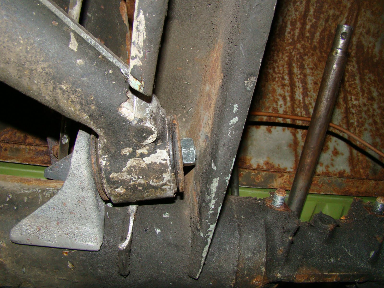
The A arm and shock was then removed and the support welded into place with a seam weld either side at the top and a seam weld inside and out at the bottom but finished flush to try and make it look like I'm good at welding. I may add another weld inside at the top as the skin it's welded to is thinner on the inside of the chassis than the outer where the original mount was welded. I have seen a shock mount  welded on the inside rip away from the chassis, so I will have to consider this.

I had one last bush to trim to size, so I used my new toy which took 5 minutes..

I could try and sort out an anti roll bar but I'll recondition the hand brake shoes first, sort the hand brake cable out, work out what length drive shafts I'll need and see if the wheels are straight and square with each other first.

Heres the parts I've made or had made to get this lot to all fit together.
With a couple of used tyres slung on the wheels the van is finally on the ground with its new rear end. This has taken a lot of work, too much time, mental skills and help from a few friends but is now finished (nearly), so up yours to who ever told me it could not be done.

944 A Arm Fitting


Sorry I deleted this post by mistake by publishing over it from Microsoft word. I was trying to be clever and it didn’t work, it was Late OK. So I've had another go at wrighting it. If you’re back for another look It may be a bit different.

The rear surspension has been on the back burner as Ive been waiting (and still am) for some custom dropped spring plates to be made for me that will fit the porsche A arm bolt patten. I got these billet ali machined spaceres drawn up by my mate Tim and made by Cranford engineering. these cost a bit more than I expected to pay but I did get quoted some rediculase prices.


This is the 924 rear axel with the hindge brackets cut away from the torque tube, Each bracket was then cut along its welds to separate it from the cut away part of the tube. This took a little care as I needed to keep these brackets in as usable condition as possable.


I did make up a wooden block that fitted the curve of the tube that fitted between each bracket so that I knew there position when cut away, but I think Ill just end up using the A arm hindge points as my referance.


The brackets were then sand blasted on a very hot day in a very hot garage with sweet dripping onto the blast cabinit window and rubber blast gloves feeling like a vets visit to a cow shed. Here's the outer in its position, With much deliduration (that’s a long word for 01.47 on a Monday morning)I decided to fit the inner bracket cut down and rotated 180 deg on the inside of the top hat section.
 Heres the view with the machined ali spaceres bolted in place and the outer hindge bracket some where it should need to be welded. I would prefered to weld these up with the new spring plates and new rubbers fitted. But may run out of other jobs to do before the parts arrive.

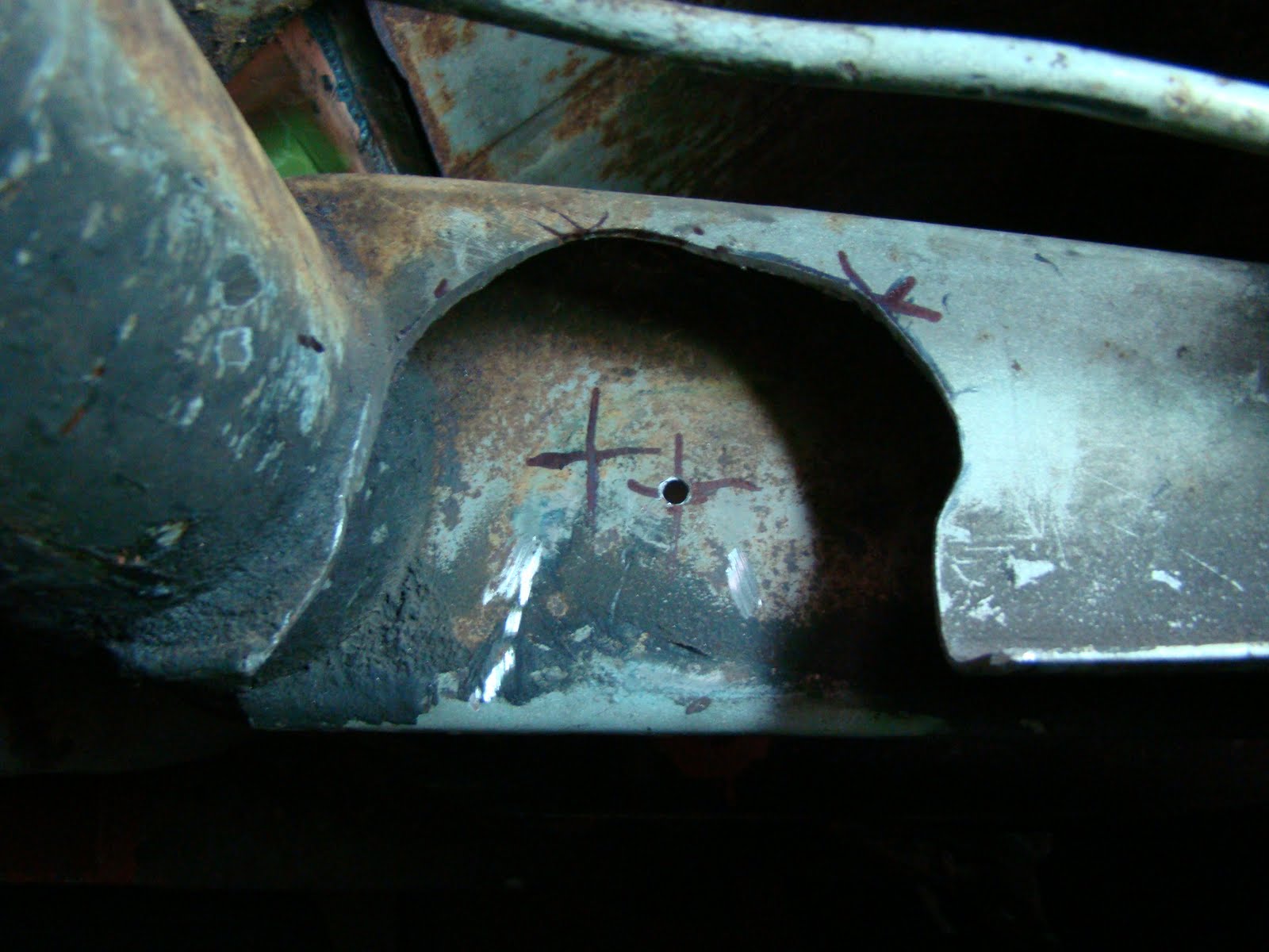
I repositioned the spring plate on its splines horisontaly, to get a good datum position before welding the hindge brackets in place, this ment cutting more material out of the channel nearly up to the top bend. This made the fixed nut for the break pipe bracket very close to the hindge point. It also took a couple of guesses to work out the correct position for the clearance hole needed for the hindge bolt. Remember measure twice....
I used the corn flakes packet to work out the correct angle I needed to cut the inner hindge bracket.


Once cut and cleaned up with a wire wheel It needed a bit of bending and cutting at the tips to get the best fit on the inside of the gearbox mounting strut. I used a marker pen on the cutting edge to show where the bracket rubbed when fitted so I could file the high spots to make sure that the bracket would sit flush.


Now ready to take the take the plundge I assembled the arm again, clamped it in position using a spacer to keep the arm away from the torque tube and tacked it in position. Then using the hindge bolt positioned the inner and tacked that on the lower edge, then clamped it ready for welding.


I played around setting up the mig and had a pratice on some scrap, as Ive never welded such thick material before. It went OK with a couple of tries I then built up the courage and welded the brackets on. It wasn't easy doing it upside down and part blind. the outer bracket needed a secoun pass just to make sure it did'nt go any where.


944 porsche brembo break caliper restoration

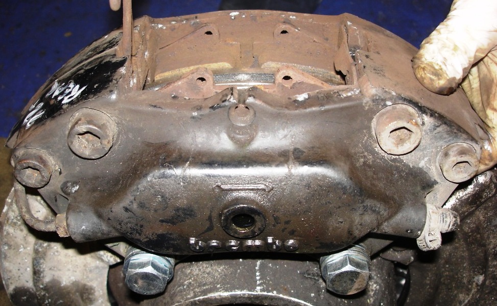
These brembo callipers are from a 944 turbo. I got from e-bay, when they arrived after a clean up I noticed the break pad slider plates were lifting due to the corrosion under them, This I believe is quite a common problem for these, Its a bit of a bad design having aluminum, steel and stainless steel all attached together its just asking for dissimilar metal corrosion. the photos are from my phone so not the best.

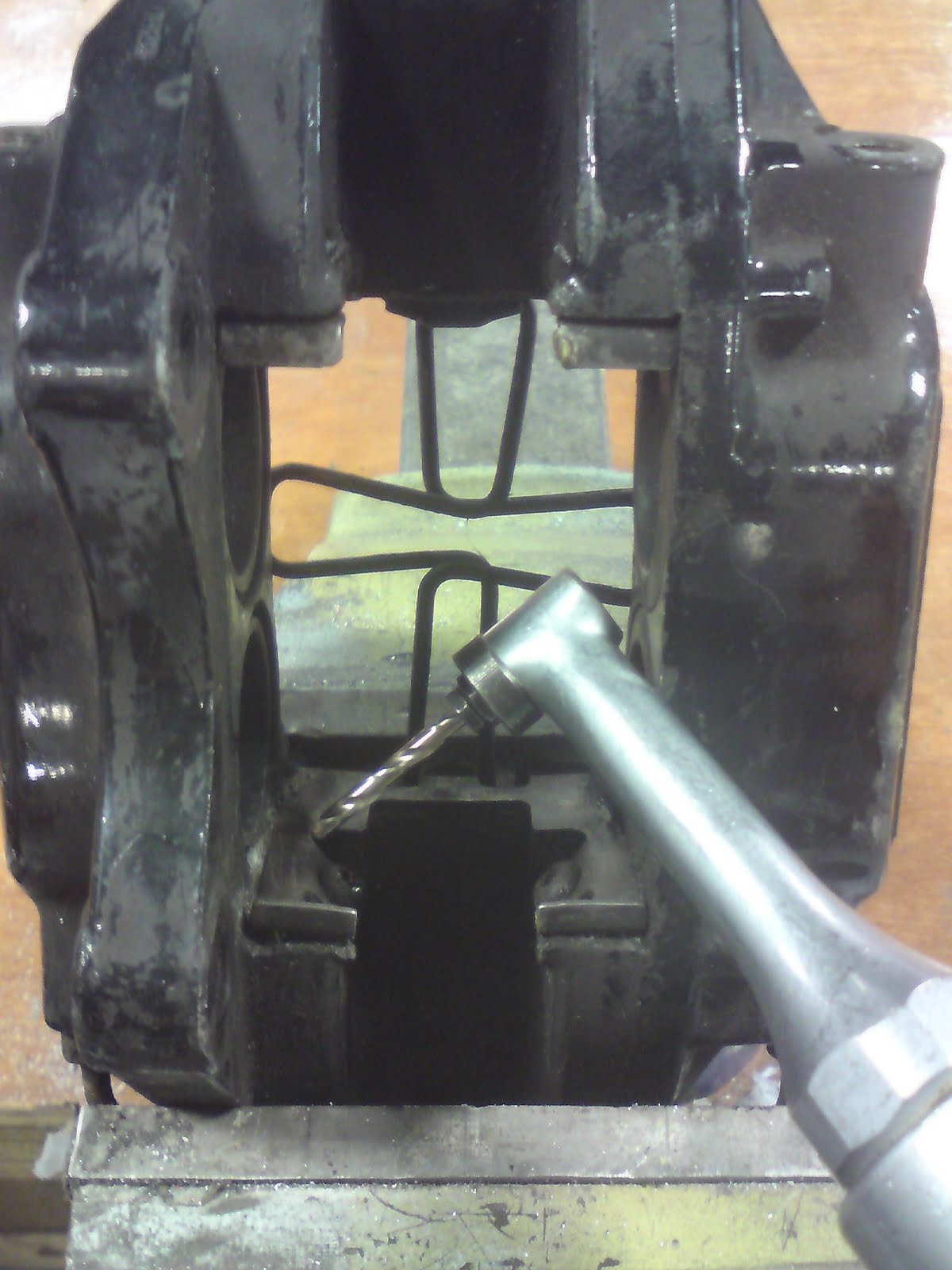
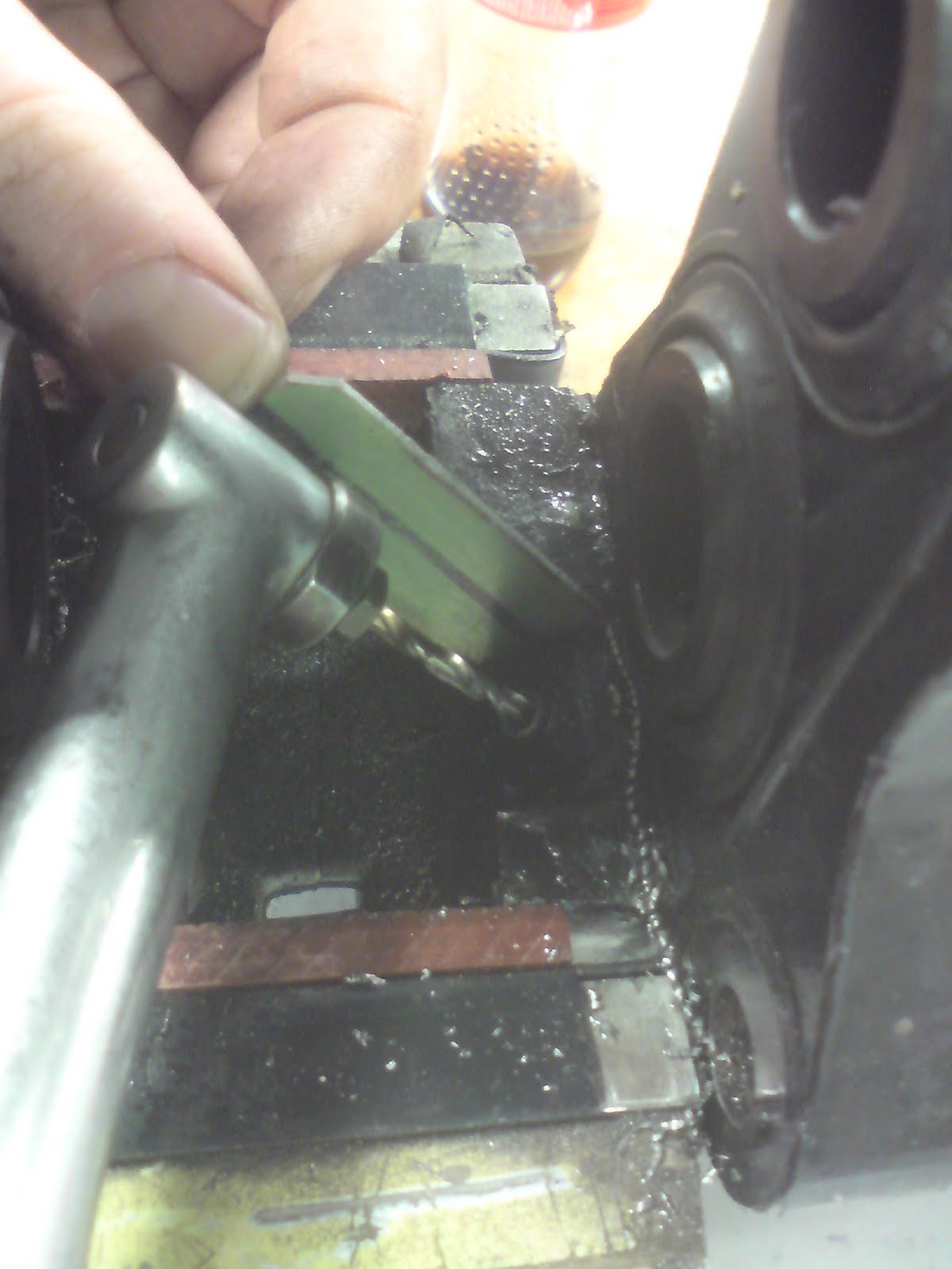
So to get these off I first tried the torque bit but that of course just rounded the rusted heads off, So this job just got a lot harder. I got hold of a 90 degree air drill, these drills have specific sized collet's that allow 0.5mm-5mm drill bits to fit to it. I had to shorten my drills so they would fit inside the calliper.

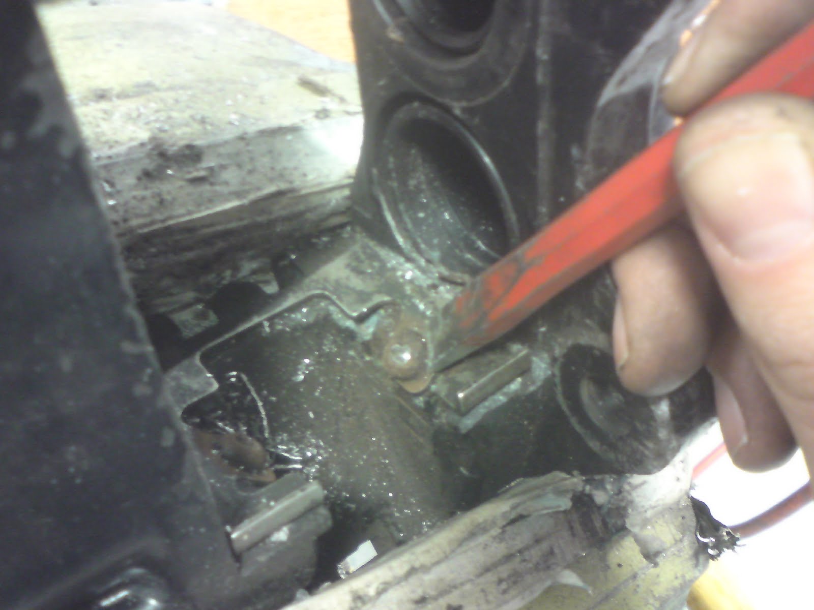
I started by drilling in the center of the head down to the plate just below the head of the bolt, this allowed me to chisel the head off each bolt. Once all the heads were off the slider plates just pinged off with a lever from a screwdriver.

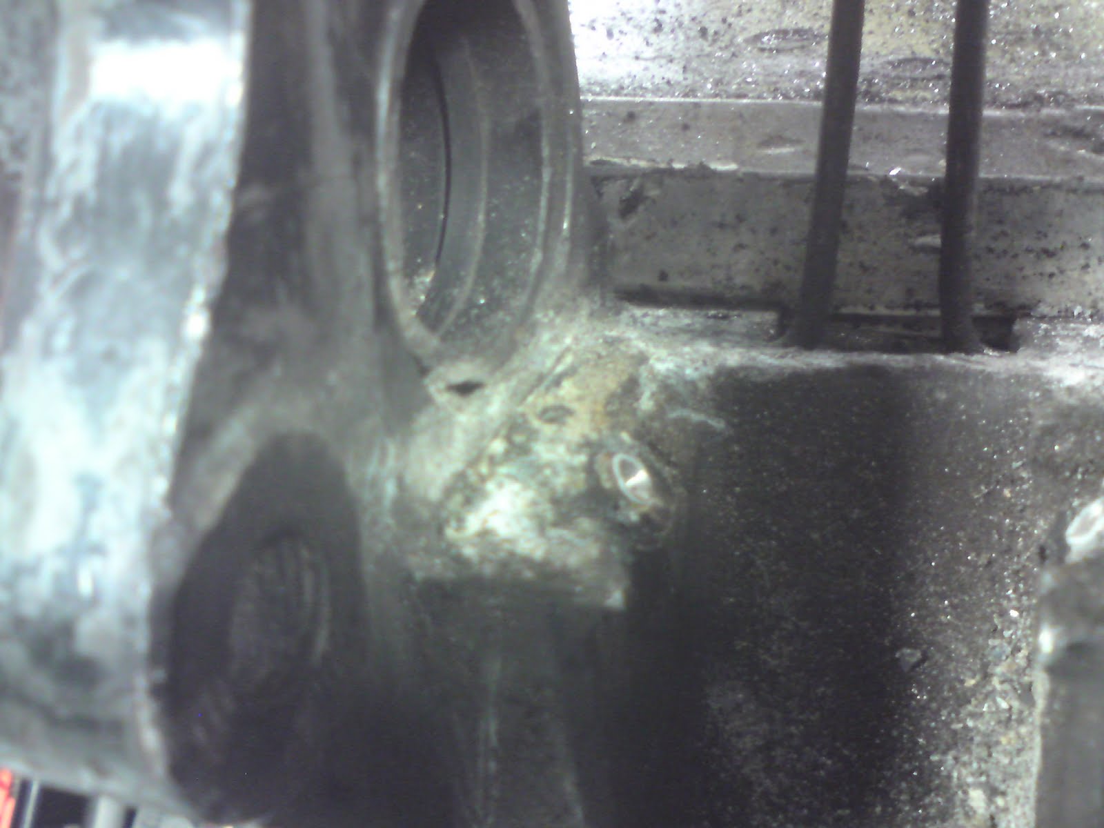
I was left with a clear view off all the aluminium corrosion and a seized bolt with out a head. I then used the existing drill hole in the head to start drilling into the shaft with a smaller drill.

To make sure I only drilled into the shaft of the bolt and not into the calliper body I drew a 90 degree line on a scrap piece of plate to use as a visual guide as i drilled. There's a gap at the bottom of the bolt shaft so you can tell when the drill has cut through the bottom of the bolt.

Once each bolt was drilled I used a snap-on screw extractor, this type allowed me to use a spanner on the shaft because a normal screw extractor and tap wrench would not fit inside the calliper. These screws came out very easily once the pressure from the pad slider plate was released.

944 IRS Conversion A arm trial fit

With the all the dimensions we previously measured, my mate drew up a comparison drawing on CAD overlaying the VW set up over the 924 rear end. This gave us a better idea what would need to be cut away from the rear end and any issues with clearance. I had also measured the old 924 spring plates and transferred the holes using a pillar drill for accuracy on to the van spring plates, I did nearly make a mistake drilling in the wrong place, luckily I caught myself by measuring twice (and only cutting once). Once both plates were drilled off I cut one to the desired length. Not knowing for sure how thick the spacers would need be I also cut out a recess for the A arm casting to clear but I realised later from trial and error I didn’t need to.
The A arm was first trial fitted with 26mm shims made up from £10 worth of cut-to-length steel tube, 14mm nuts, washers and threaded rod, this clunkingly amateur set up gave me an idea of where I needed to cut the chassis for clearance.
So now the point of no turning back! I got to work grinding away the chassis to get the clearance needed for the travel of the A arm.
With the A arm remounted with 26mm spacers you can see the hinge just inside the horn.
Then with the wheels mounted directly on to the hub, with no discs or caliper spacers, the rim clearance on the wheel arch was too close for even the tyre to fit.
I did fit the discs and calipers to the hubs to see how they would look then try to fit the wheel, this reminded me I needed to shim the caliper lateraly to the disc (placing spacer washers inside the caliper mounting holes and onto the arm mounting position) and space the wheel off the disc about 6mm to clear the caliper, (see previous blogs) this meant spacing the A arm even further in than expected. But don't the disc and caliper look lovely?
With several hours spent fitting and dismantling the spring plates, grinding out the chassis a little more, cutting tubed spacers and threaded rod to length then refitting it back on the van, I finally decided to use 57mm lengths of tube to space the A arm in from the spring plate. This gave the 205/60 /15 tires about a 24mm clearance gap from the wheel arch and 18mm gap from the face of the spring plate. The problem now is that I can only fit the wheel over the disc and hub when the spring plate is set on the original spline (touching the bottom stop). I also need to work out where the damper mount and bump stop will fit. It's a good job the wheel and tyre aren't heavy...

944 IRS conversion

Taking a break from all the welding and body work, I managed to drag my mate Tim from working on his own van to spend the day removing my rear end and measuring up for the sexier back side. On the VW not my own body. He's not an amateur surgeon. Just to clear that up... This is a Porsche 924s (not a 944 as stated in the title but I think they are the same) rear axle that I ordered from Porsche Apart and it arrived in a box as wide as my garage, doing a little VW to Porsche IRS conversion research online I've found that there are two types of 944 aluminium A arms, one shorter than the other, I hope I have the right one. I've also had a few comments that this can't be done so lets see if they're right.

I've played with the hubs and discs previously (usually when I'm alone in the house) but it was now time to get the serious stuff sorted out. So a quick spray of penetrating oil on all the bolts and the original gearbox and reduction boxes pop out after 40 years with no bother.
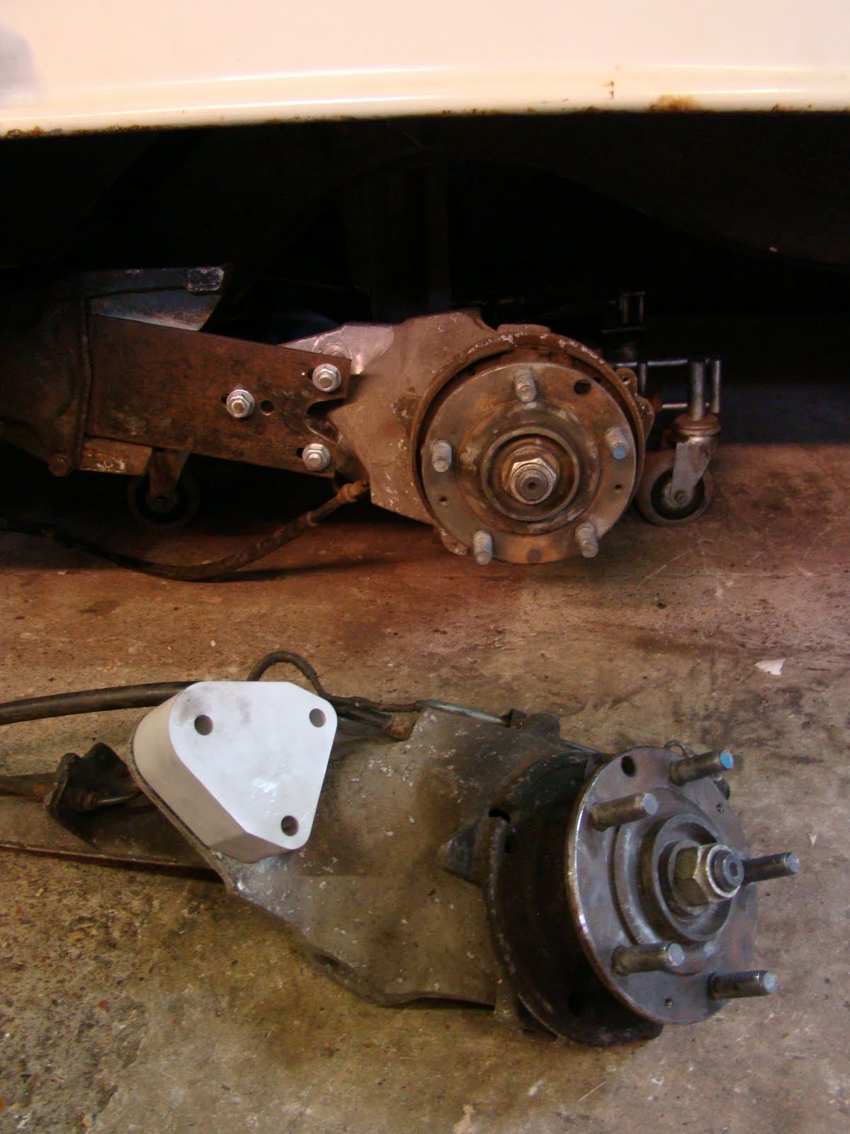
Here are the A arm mounting points on the 924s beam, this beam is the same diameter as the bus one at 90mm. I may try and use these mounts if I can't work out how to make a fresh pair.
The mornings' work gave us the measurements we needed to calculate the size and shape of the A arm and most importantly if they would fit. I've drawn up a plan of the measurements to get an idea of how things are going to fit (the arm on the drawing is a bit fat). The Porsche axle wheel offset including discs worked out to be 1497mm across, the Bus axle with the original reduction boxes and drums came up as 1445mm across. To keep the outer wheel rim in the original position under the arch and using wheels with an extra 40mm offset means I'll need to locate the A arm mounting points 46mm closer to the center line.
I've also stolen a couple of photos from the SSVC 'For Sale' forum of a 944 rear end and edited them to show the comparison of the different length arms below. Please don't sue me if you hold the copyright of these pics. The longer arms have no bump stop molded in the arm and a longer reach from the spring plate mount.
Before we removed the spring plates I marked their position across the spline shaft with a junior hacksaw then carefully slid them off making sure the inner portion of the splines stayed in position, if the moved I'd have to waste a lot of time later setting the ride height to the correct set up. The 924 spring plates are a lot shorter and made of two plates, the outer plate has the inner spline tube poking out (the spline is smaller than the VW one) the tube is slid through the inner plate and held in place by the two bolts one is elliptical used for adjusting the ride height, the plates are sandwiched by rubber bushes and bolted on in the same way as VW do it. With the reduction gear boxes out the way we decided to see what sort of ride height would look good. These are 205/60/15 unfortunately they are touching the top of inner arches. But you must admit it does look good! (No the grass isn't real, I R Photoshop King)

Machined front caliper mounts

Every day priorities like moving home, exams, barbeques and playing new playstation games have unfortunately put the van's rebuild on the back burner for the last month or so (I just don’t want to miss out on any of the summer sunshine, you never know how long it will last). But I have managed to get the front caliper mounts machined.
A friend that knows their way around a CAD program was able to help me in a morning produce an engineers' drawing. We started drawing all the known dimensions e.g. brake disc size, caliper size and spindle mounting hole pitch, from these we were able to calculate all the dimensions required for the mount, then with an outline added we created the virtual caliper mount. This wasn’t far from the rough sketch I'd made in the garage to produce the wooden prototype, the hardest part was calculating the curve that would match the profile of the caliper inner mounting lug.
I sent the drawing to a local machine company (Cranford Engineering) that was able to do the machining at a decent price. I chose solid steel as I didn’t fancy trying to calculate the strength and shear properties of aluminium. I was very pleased with the end result, with a clean up, coat of paint, a few new bolts and the front brakes will be ready. Unfortunately I won't be able to test them until the van is rolling.

Porsche brake conversion Pt3

I think I've been a bit sidetracked sorting out the brake conversion instead of getting all the welding completed, probably because it's more fun seeing shiny bits coming together.

The problem with the rear disc diameter being too small was solved with replacing the 944 >88 discs (289mm diameter) with 944t (928s2/928s4) 299mm diameter ones, these new rear discs are a little thicker at 22mm making it a squeeze fitting the caliper when they have new pads. The new disc cost an extra £30 a pair; this reminds me why I have a Vdub and not a Porsche.


The caliper is a pretty tight fit in the back off the 15" wheels; there is a slight rub on the wheels' inner shoulder where it rubs on the front caliper face so I'll need a wheel spacer of about 6mm to get the minimal clearance all around. It's not what I wanted to do. But it's something I'll have to live with.

Trying to find 14mm washers in the local DIY shops to use as wheel bolt spacers was harder than expected so I've resorted to using 15mm plastic water pipe. I first cut them 7mm thick that didn't work, then at 9mm and this still rubbed in a few places on the inner wheel, This meant pushing the wheels this far from the hub gives me the next problem of having to use longer wheel bolts, so I may just space the wheels enough to get to get 4mm spacing from the caliper keeping enough thread for the wheel bolts and clear the small amount of material from the caliper to clear the foul.

I popped down to a local Porsche show room in my bug to collect some caliper mounting bolts, after a scan of the 911,s I was greeted by a pretty lady behind a desk asking if I would like any help, explaining why I was there and a phone call later a suited gentlemen arrived with my £6 bag of bolts, a little surprised I paied and started to ask about caliper piston sizes and brake master cylinders, "sorry I don't study the breaks" silenced I decided it was time to leave. You can't beat speaking to a grubby mechanic who knows there way around the cars they work on.
With new bolts I mounted the front caliper to the wooden bracket I'd made and with the bearing spacers fitted I was able to work out that I needed 11mm offset to centralise the caliper on the disc. I'll now have this bracket machined once I decided the best place to position the caliper around the spindle. Although I'm still unsure if I should use my link pin or ball joint spindles and beam.