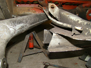
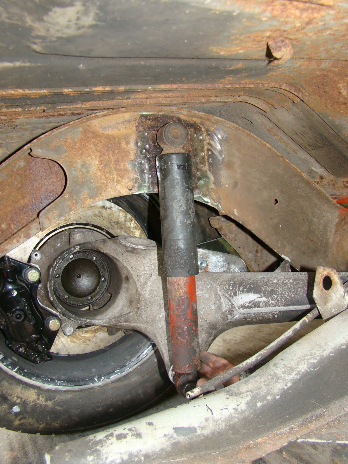
To fit a shock/damper from the 924 A arm to the chassis of the van is probably the biggest problem I've had with converting the rear suspension to IRS. One of the problems is that the curve of the gear box mount kind of gets in the way. Thinking I could buy a shock mount and weld it inside the chassis rails is not that easy.
So I decided to get the gearbox support out the way, I didn't take this decision lightly it took months of staring at my rear end thinking how to mount the rear shock. I plucked up the courage and went for it, drilling off the spot welds and cutting away the lower portion.
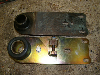
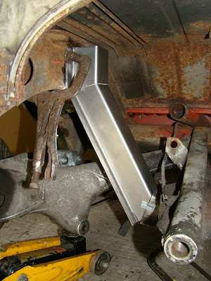
 Once the curve was out the way I had the room to play about with different designs to see what would work. Here's a cereal packet cut and taped to make a wider top hat section that the original one to allow the shock to fit inside.
With the top hat cut out I took the measurements I needed and bent up two more sections to replace the one I'd cut away.
I had a lot of trouble try to get hold of the lower shock mount bolt that fits the 924 rear swing arm which is M14 x 1.5 x 85 (part no 900 082 054 02) as Porsche no longer make them. After a long search on several forums I ended finding out about a stronger spec bolt from BMW the same size as the one I needed.
 With a cutoff of new folded section I trialed the best place for the mount to fit. I now found that the lower bolt was at a slight toe in angle and tilted the top of the shock into the centre of the van, This meant there was not enough play in the rubber mounts to take up the now angled position of the shock. I tried to sort this by buying some Creative Engineering shock mounts, these would allow me to turn the top shock hole 90 deg. But to fit these I would have had to drill through the chassis and it would have been easier to just weld a tube between the two skins of the chassis.
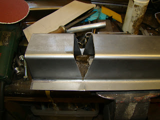
 Taking the angle from the cereal packet template from earlier I cut and bent the top hat section for a trial fit over the shock.
 Again after another mammoth search I was able to get a pair of custom shocks from SPAX made with ball joints at either end to alleviate the problem of the lower shock bolt being at an awkward angle. To spec the shocks using Spax online chart I worked out the extension and compression to give me the total movement, then worked out what ends I'd need, then added a built in bump stop.
 Spax also helped me by providing a couple of aluminium spacers to pack out the gap between the 14mm lower bolt and the 15mm bearing, these would usually come with a 12mm spacer that I had it push out to fit the spacers. I cut the larger bump stop off the shaft and worked out I needed a 10-14mm spacer to pack out the lower mount.
 Again using my cardboard template I marked then cut the angles in the top hat section and drilled a hole at the tip of the cuts for stress relief in the bend.
I then cut the original section to the angle I needed. I should have left a lot more material on this part so that the angle of the top mating pieces were equal as this would have made a neater joint.
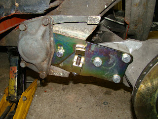
 This is the section trial fitted, I'm hopping to spot weld the top section to the chassis. You can see where the lip of the lower portion don't come together because of the uneven angle where the two meet
I'm not sure how but the profile of the new section didn't match up with the old one. I thought I had this spot on. With a bit of thought on how I can make this fit, welding it together with a lap joint or just beating the hell out of it. I decided it would be better to fold up a new piece.
Instead of putting that to one side due to my cock up, I decided to use this as a trial piece for the shock mounting position. I grabbed a few large washers and spacers from a shock mount I brought from Demon Tweaks that didn't fit. I then welded up the seam at the bend and fitted the shock in the top hat section with a 1/2 inch bolt that went all the way through.
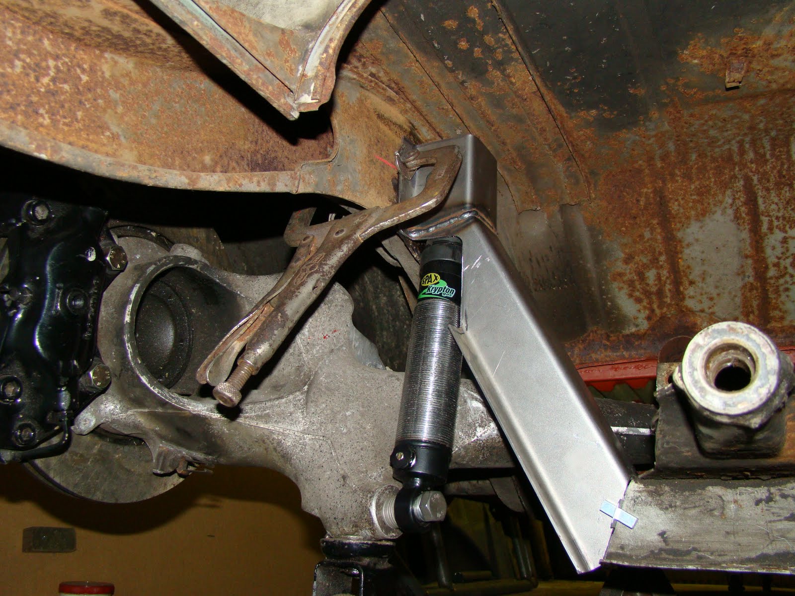
With the shock at full extension and the A arm at full drop the shock was a little lower that the bottom mount point which meant my calculation for the extension worked out OK. 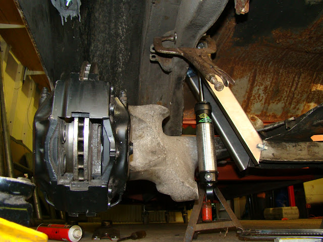
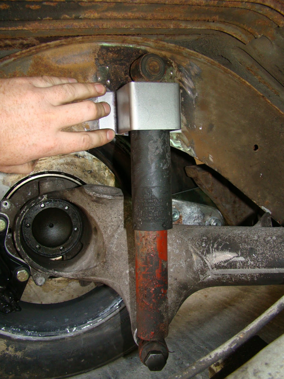
Plenty of clearance inside the box section for the top of the mount.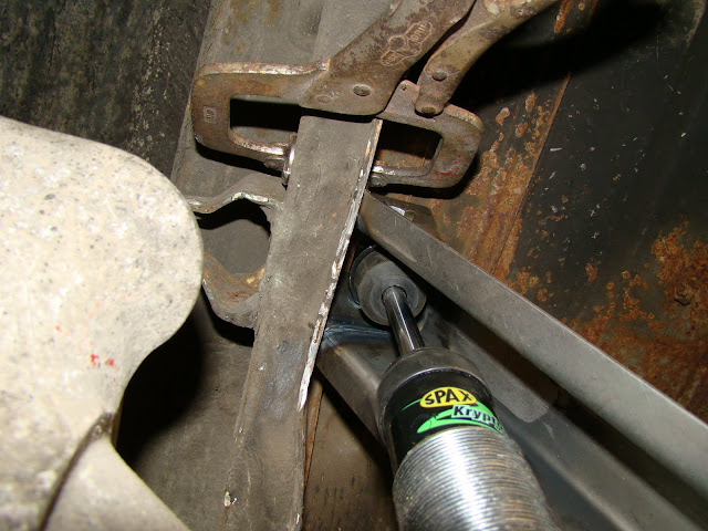
Then compressing the shock It all went Pete Tong (English rhyming slang my American friends). The body of the shock fouled on the back edge of the section, because as it moves up the lower mount also moves slightly back. After half an hour of huffing and fiddling I decided to cut away the fouling section to see where it should sit naturally. Getting a call from the house for Sunday dinner I've had to leave the problem there for now, and have passed the details on to my design consultants. Hope they come up with something, as I haven't got a clue what to do. Maybe I shouldn't have cut the original support out!

.JPG)
.JPG)
.JPG)
.JPG)
.JPG)
.jpg)
.jpg)
.JPG)