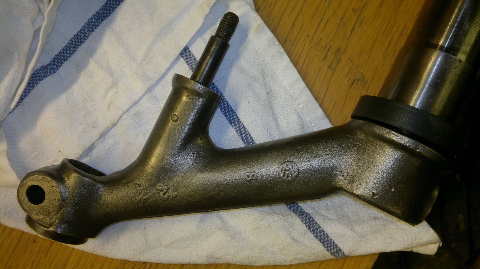
After narrowing my front beam trailing arms I fitted them to my new narrowed front beam but the new beam did not come with instructions. The nylon bushes inside the tubes were smaller than the bearing surfaces of the trailing arms, but I found this out the hard way.

I'd pressed the trailing arms into the tubes with a few big swings of a large mallet to find the arms would not rotate once home, and I'd pushed the outer bearing into the tube, this made me wonder what Id done to the inner bearings
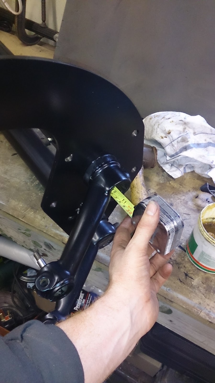
Using a measuring tape I was able to feel and measure that the inner bearing was pushed in over half way. It was a heavy hammer.
After a lot of pondering and a few trial wack's with a hammer I realised I needed to use a pulling tool get the trailing arms back out. So I made a pulling disc that was threaded and machined just under size of the outside diameter of the trailing arm with a step on it so that it would fit inside with out moving, two flats were filed on its edges so it would fit inside the adjuster slot.
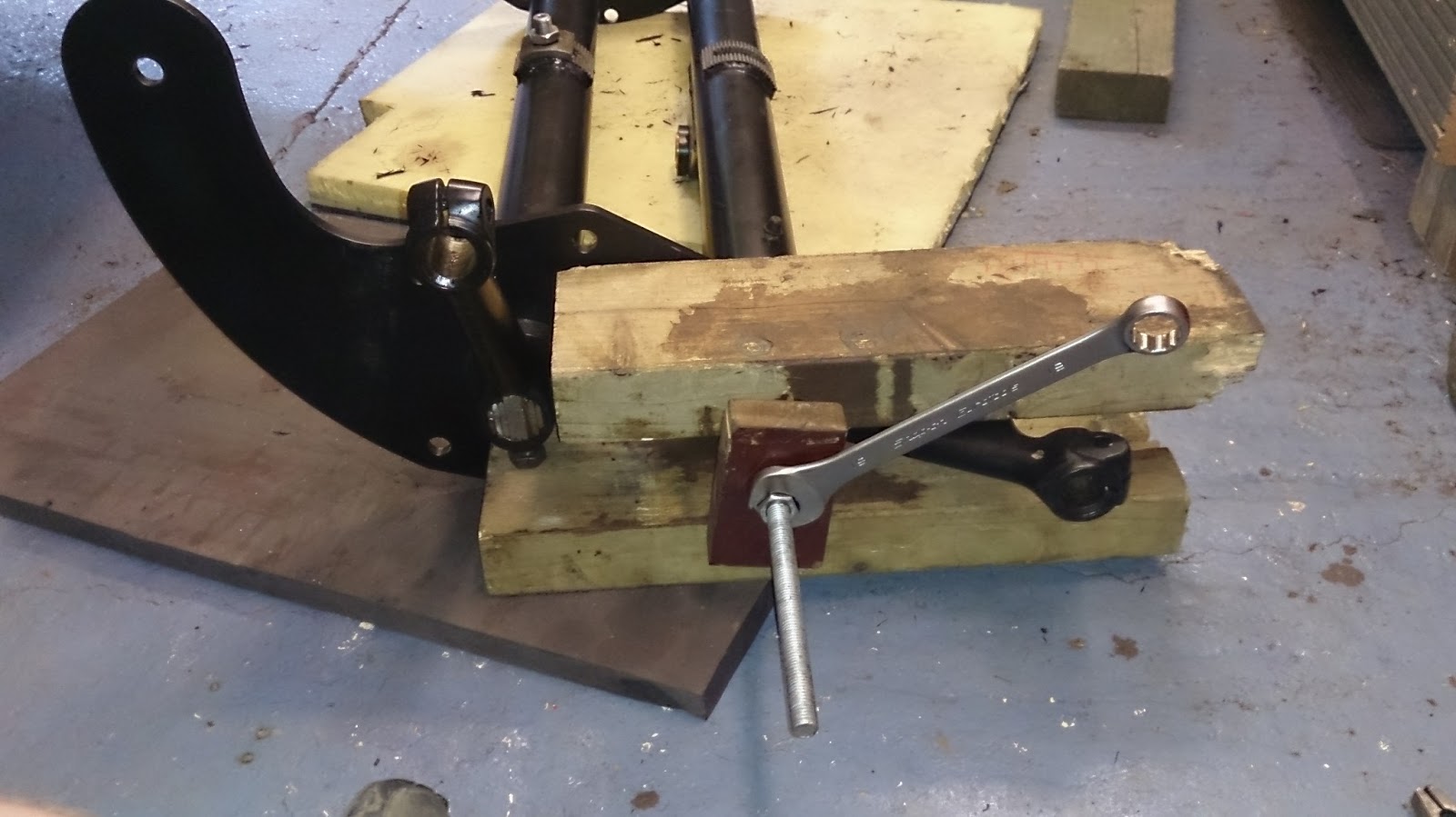
The adjuster bush inside the beam that holds the springs plates in the centre was slid to one side and the plate held with pliers in the hole was attached to the m10 threaded bar. A few blocks of wood held over the trailing arm and the arm was would out with out to much trouble.

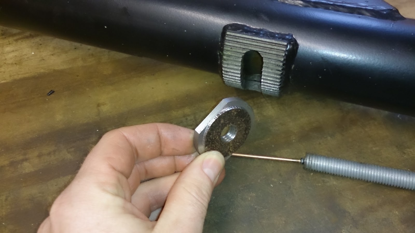
Here's the plate attached to the end of the arm once it was removed, the pin from a dent puller was welded on the end of the threaded bar to help guide the two together when trying to thread them inside the beam. This plate is now just lying around the garage so if you need it to let me know.
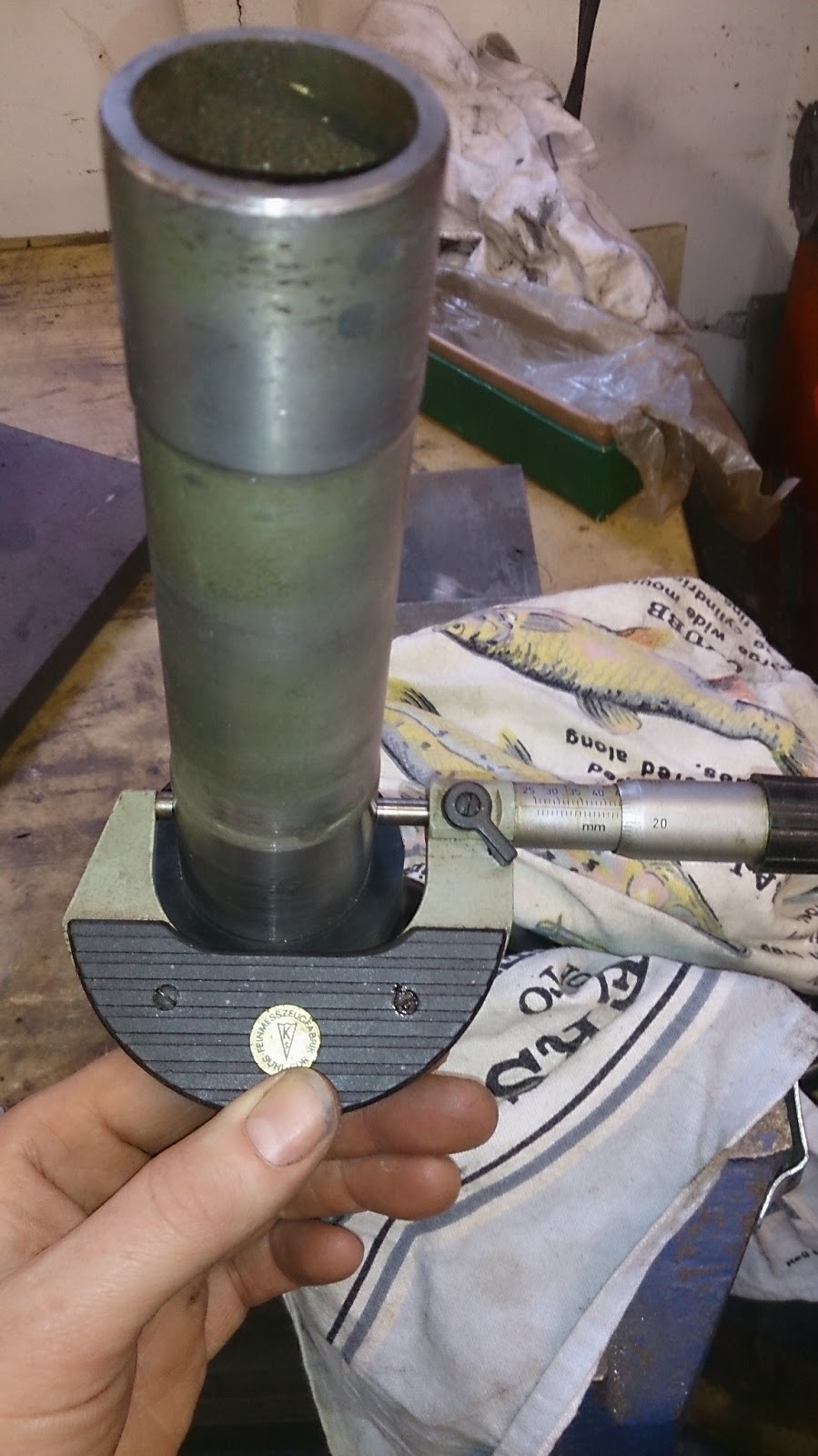
With all the trailing arms removed I decided to measure the bearing surfaces before installing them this time. There was about 0.002"- 0.004" interference between the bearing inner surface and the arms.
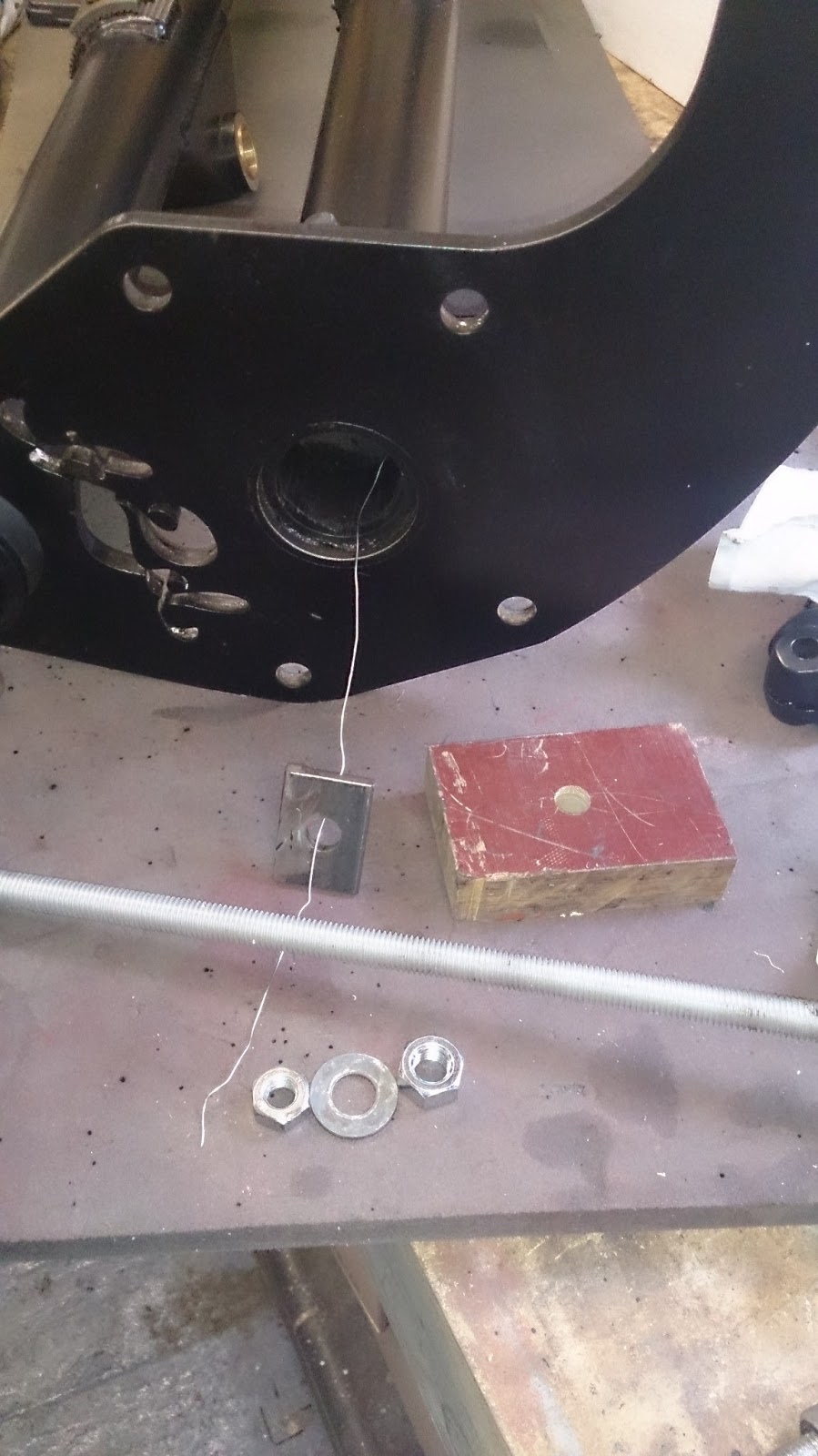
Now to pull all the bearings back out to there correct position I used a plate cut narrow enough to fit through the bearing with a hole big enough for 10m threaded bar to fit through once vertical the 4 corners would pull on the bearing inner face.
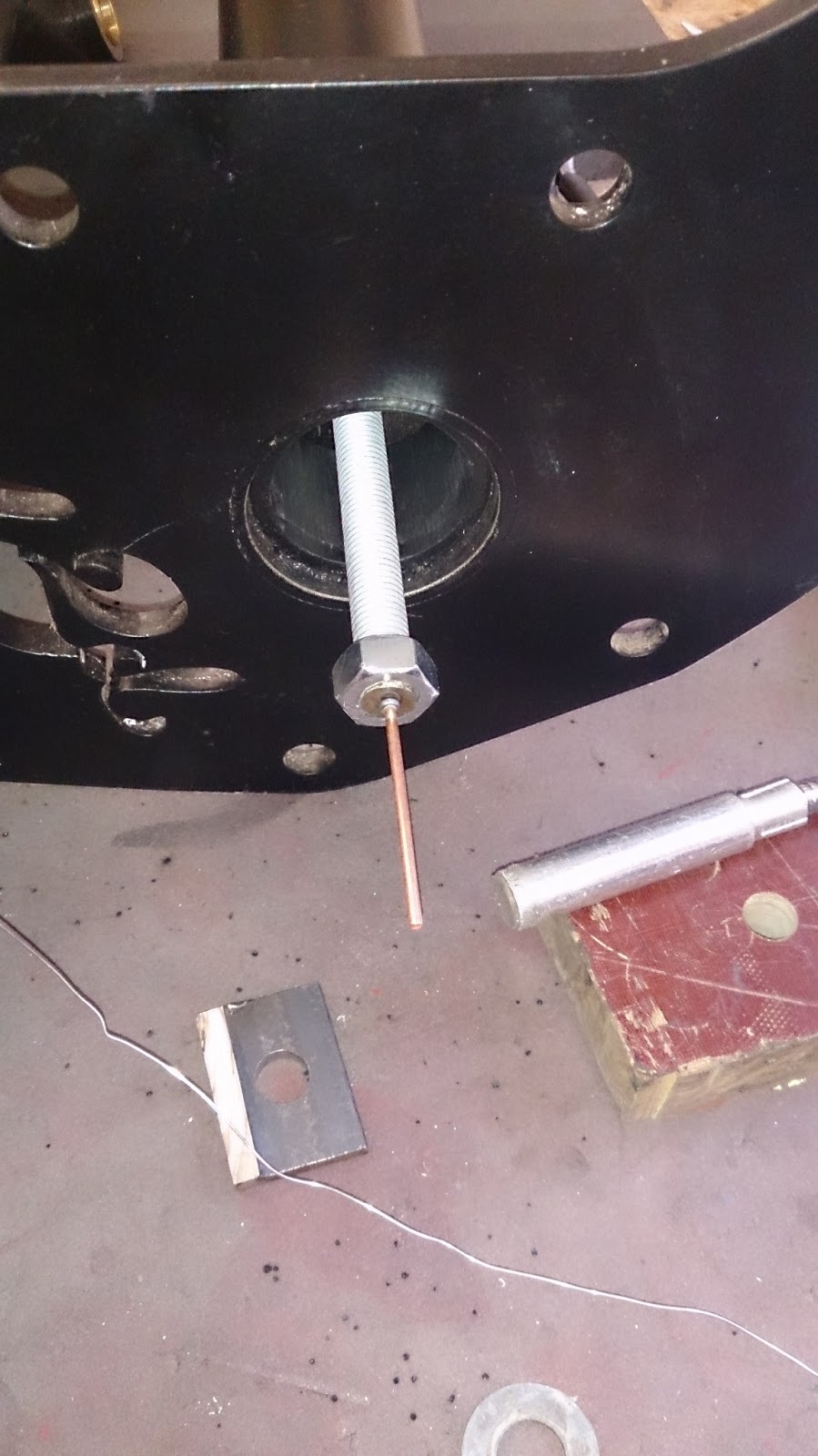
I used the pin welded on the end again to help attach a nut I also tried using a magnet to hold the plate in the correct position inside and passing the threaded bar in the opposite end with a nut attached to hold the plate.
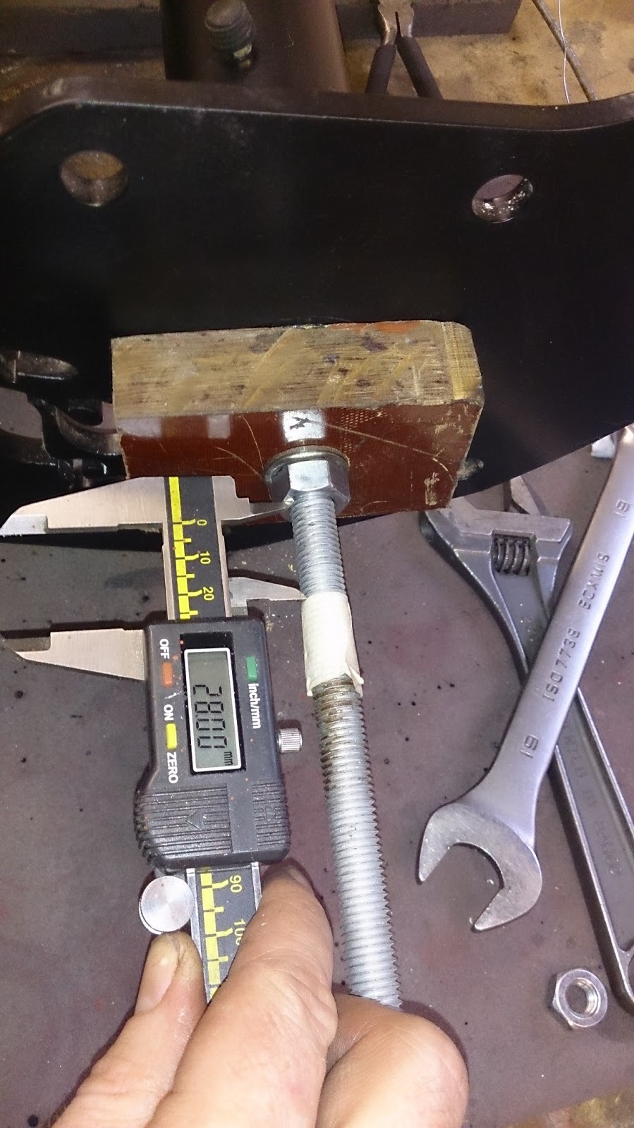
A block of wood and second nut was tightened on to the threaded bar, then using some tape and a measuring tool I screwed down the thread to pull the bar out the desired distance and move the bush back to there correct positions.
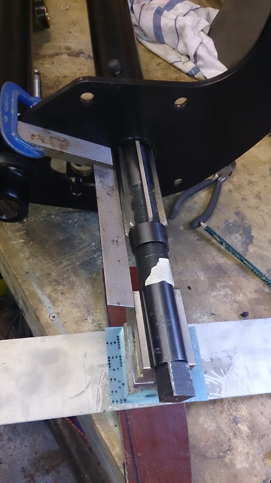
The next task was to cut the bearings to size, I didn't want to do this gashly, so a post on the ssvc forum and help arrived from VW Jim in the shape of an adjustable reamer.
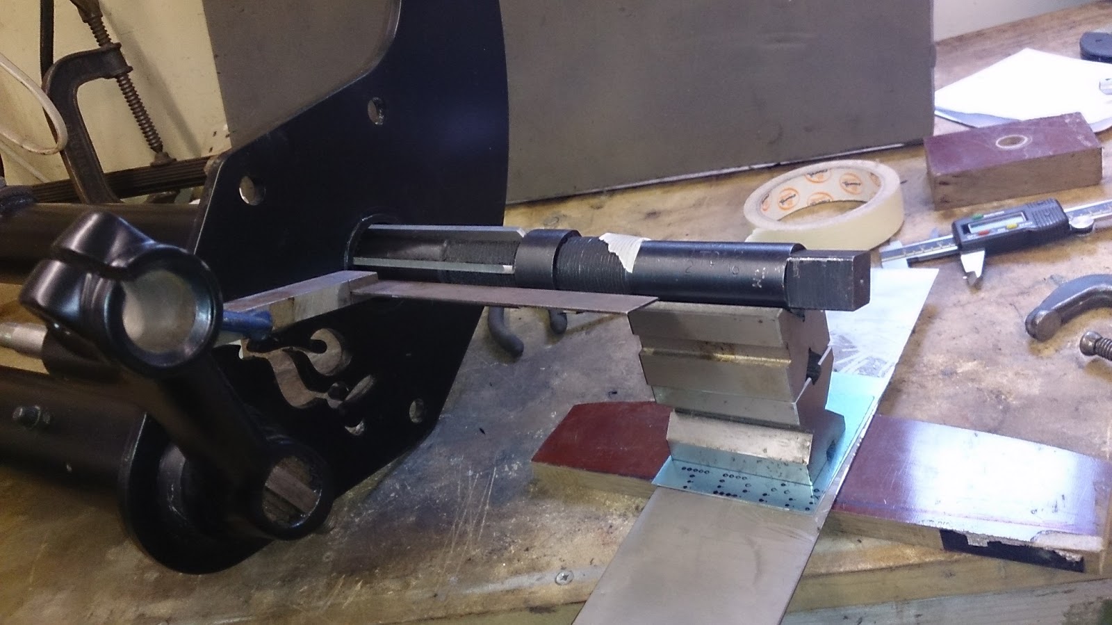
Although the size is pretty big this is a hand reamer, It took a bit of adjusting to get it to sit square so I could cut the bearings to the correct diameter, an interference fit of 0.000" - 0.001"
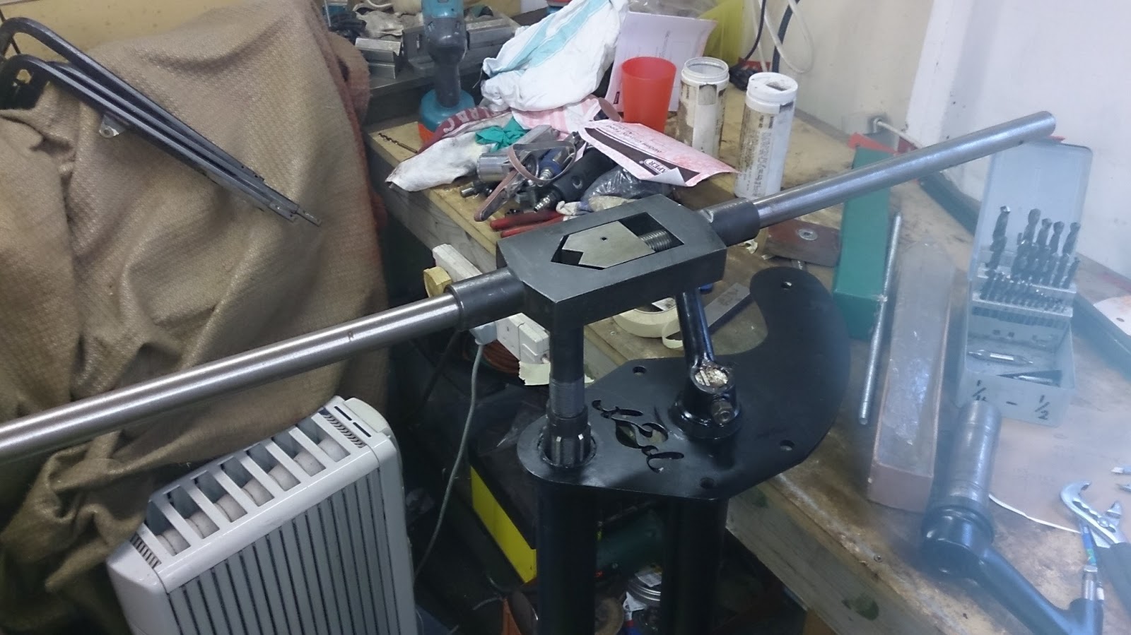
Another chat with some colleagues about how I was getting on with the van restoration lead to getting my hands on this tap holder for giants. This was cumbersome to use as I'm not a giant, but made it easier holding the reamer square.
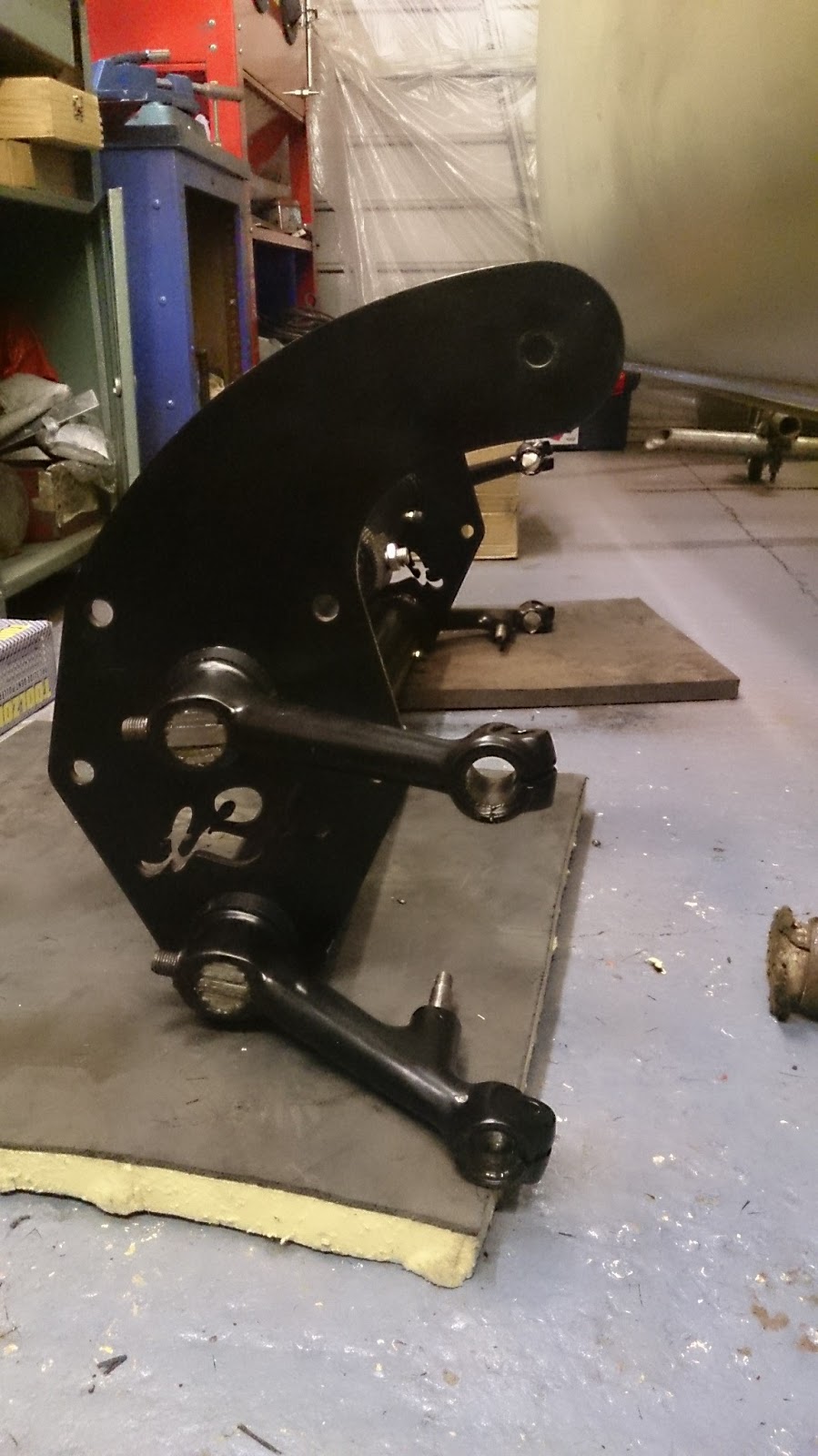
With the bushes reamed and the trailing arms fitted I finally have a front beam ready to install.