This was the rusted cab floor
.JPG)
I repaired it earlier but now needed to fit the hinge and pedal back in position.

I brought a pedal hinge from custom and commercial.

Using the pen lines I had drawn when cutting the old hinge out this with a drill bit through the holes helped keep it square and lined up.

I counter sinked the two holes to help get a penetrating weld, you can see from the pen lines that I nearly fitted it the wrong way around.

I then moved onto repairing the hinge on the accelerator pedal

I whittled this little piece from a lump of square mild steel bar and drilled the holes to suit the hinge pin I brought

I then had the idea of fitting 6 mm track rod ends to a lump of steel that I'd weld to the pedal. But they looked to big the weld would have looked ugly and a bit of over kill.

So i decided to open up the oval hole in the pedal and make a bush to fit a 5 mm ball joint

The bush was turned with an interference fit and squeezes into place with a bench vise.

with the hindge in its position I needed to fix it in place.

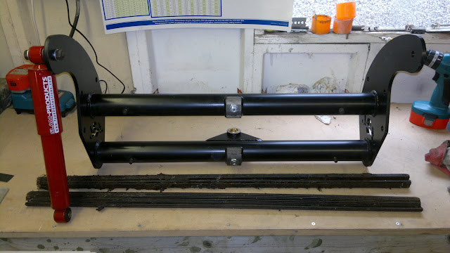
I was going to mig weld it but thought Brazing would look neater I've never braised before so this should be good.

The only thing I had to get a hot enough flame was an Arc welder and some carbon rods.

These rods once slid together ignite from the current from the welder, as they burn shorter you slide them slowly together, until pulled apart to stop them so the current can't bridge the gap.

I probably over did it with the heat and the ammount of braising rod I added between the gaps but the lower hindge is going nowhere, Just have to clean of the slag.

Under the cab floor the two angle's that hold the drilled out nuts where the rod goes through to link the pedal to the cable were also oval from ware. I opened these up, but had to cut a drill bit down to fit under the floor.

I then made a couple of brass bushes to squeeze into the holes that would fit an 8 mm round steel bar.

I then cut, radiuses and bent a piece of flat steel bar and turned a tube with a shoulder to fit in the lower end braised it in place and drilled a 5 mm hole for the ball joint at the other end and taped a hole fro a 4 mm grub screw.
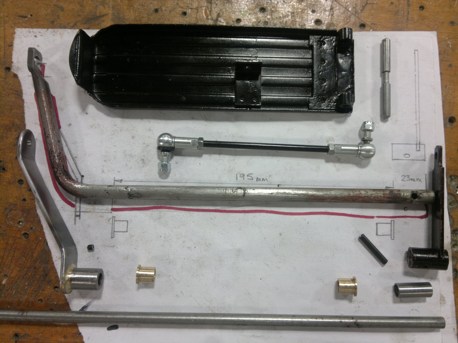
These are the parts laid out ready for mockup.

Then put together on the bench.

I then painted them up pushed the bushes on the rod, that scrape the paint off. assembled all the parts and then drilled through the grub screw hole to make a dimple to locate the grub screw once the angle a position was correct.
There was a little friction in the mechanism I probable put this down to not drilling the brass bush holes parallel to each other.