Converting the Garage to a Workshop

I've had the pleasure of becoming the proud owner of a 1950 lathe, a pillar drill and a small milling machine.

The trouble is where to put them, the garden shed is full of rubbish, Rachel said its a no go for the dining room, so I guess I'll have to re arrange the garage. 

With the van wrapped up and moved out of the way on a shopping trolley. Rachel (after possibly feeling bad for not letting me take over the house), said she would help so I was able to persuade her to clear the painted part of the garage floor ready for the new arrivals. 


With some help from a couple of friends and a hire van we hauled the equipment in to its new home.

With an early start the next day I locked the dog out of the garage (she'll only turn some wooden chair legs on the lathe if she's not watched closely)  and started painting the centre of the floor on probably the coldest day we have had in 2012. This meant the paint was like treacle.

By the end of the day when I wanted to move the van back in the paint was still wet, not wanting to leave the van out I pushed the van back in on its shopping trolley, wheels wandering all over the place leaving behind a trail of fresh paint tracks and blue tyre tread. 


It finally took 3 days for the floor to dry before I could walk on it without sticking to it like a Scout Hut carpet and go and play with my new toys. 
p.s. the dog did manage to sneak in and leave a paw print on the new floor but I managed to catch her before she made a set of chair legs . 


Rear Shock Mount fitting for 944 IRS conversion Pt 3


I was able to visits my uncles workshop and turn down a couple of brass bushes to fit inside the top mount bearing this is because the bolts I'm using is 12mm and the bearing hole is 15mm. I also found out later I used the wrong cutting bit. that's a whole different world.
I also faced of one of the other bushes to give me the offset position I needed for the top mount. when at full extension the shock is vertical and the top mount collar just sits off the forward face, when compressed the shock swings back and because of the off set now sits clear of the back face.
Now that I'm happy with the top and bottom shock mounts I cat fit the new section. I removed the spring plate and A arm then clamped the lower part of the section with panel clamps and adjusted the top till it sat square with a bit of persuasion and also lined up with my previous marking of the highest and lowest position for the mount bolt.


With the upside down, on my back, stuck under the van, not able to move welding done and the spring plate and A arm fitted you can now see the final result.


I'll tidy the lower point and form a radius and then there's just the other side to do, just hope it does not take me 6 month's.

Rear Shock mount Fitting for 944 IRS conversion Pt 2

After messing up the width of the last top hat section I attempted to bend up some more, this took another trip to the metal shop and several more attempts at fabrication, all this just to get the width 1 mm thinner

With the old cardboard template from my first attempt I dug out from the pile of scrap metal, I marked out the angles needed for the bend with a small hole drilled in the corner to relieve the bend. A couple of blocks, a large clamp, 2 litres of coke and Thors' Hammer allowed me to make the bend.


A trial fit just once, twice or seven times allowed me to adjust the angles of the cuts slightly so it would fit. This meant climbing in and out of my engine bay on my hands and knees each time. I like my van to know it's the Boss in our relationship.


A couple of tack welds on the bend line while the section was clamped to the chassis rail and then it was removed to be seam welded and then attacked with the grinder to hide the bodgy welding.


I cut up some of the other section I'd made so that I could see if it was worth fitting these U sections inside the top mount area to strengthen the support but it would have been to awkward to spot or mig weld these in place and they would have reduced the clearance inside the top shock mount even more that it already is.


I also bought some brass oiled bushes, one top hat, two for clamping either side of the shock mount bearing and a third that can turn down to the required length to get the correct position for the top mount. The shock mount hole is 1/2" (12.7mm) or 15mm (with the supplied spacer removed) and the brass bushes could not be supplied in either internal size, so I went for 12mm internal with 18mm outer. This is the diametre of the regular shock mount bolts for a van.


With the position of the top mount holes calculated from the nominal extension and retraction of the shock taking into account the full range of the A arm and the compression of the bump stop. I then ignored that and drilled a couple of holes where I thought looked good. Fitted a 1/2" bolt from a Creative Engineering mount kit,  some bushes from a Demon Tweeks mount kit and a few washers allowed me to adjust the position of the mount forward and back to get the best position for inside clearance and shocks angle. 


This also meant cutting the chunk out of the section so the shock would tilt back as the wheel moved up. A few ideas were passed around by my design team as to how to overcome this weak spot and the best idea that I/we could come up with was to cover the shock keeping the existing angles. So I raided the cornflake packet again to work out what shape I'd need.


I also needed to clear the back of the section where the A arm moved up and rubbed. I cleared this originally by cutting it out with the grinder, This time I heated the section up and grabbed Thor's Hammer again to beat the whatever out of it. The blocks helped keep inline what needed to stay straight and I got to let all my aggression out. 


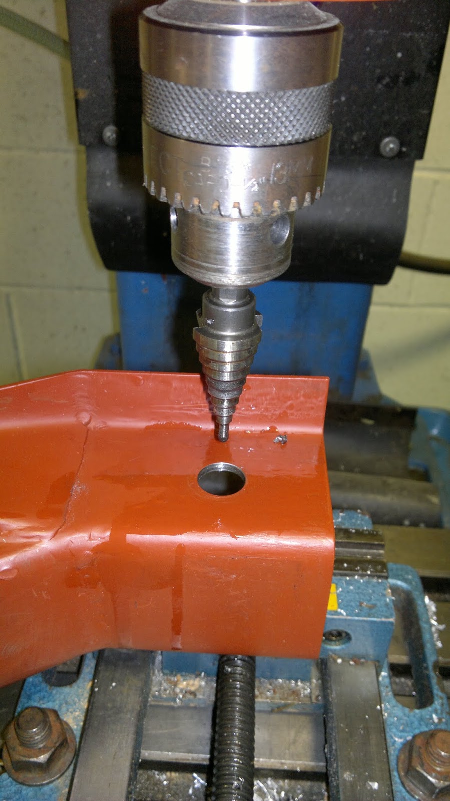
With most of the fabrication now sorted I can concentrate on getting the holes drilled for the top mount bushes. The price of a 18mm hss drill bit was £14.95 and too much for just 4 holes so I reluctantly borrowed a Christmas Tree hole cutter and attempted to drill a pair of parallel holes in an unsupported springy piece of folded steel, the use of the pillar drill did help.


To get the second hole drilled in the correct position I fitted the bush into the first 18mm hole then clamped it in the pillar drill vice, by slotting a 12mm drill into the bush and poking it out the other side I  was able to line up the tip of the hole cutter with the tip of the 12mm drill bit. I drilled away and it still looked a bit off. 


I just need to turn down the bushes to the correct length and I can then weld this side to the van and then do it all again for the other side. Whoop whoop.


Battery Tray Repair

My battery tray had been ignored until I started messing around at the rear end and started removing the layers of flaking rust I found sitting back there. I thought about patching the holes but for the sake of £25 I'd replace the panel.

After a trip to Bug Jam I picked up a Creative Engineering replacement panel and started hacking the old battery tray out. Starting with a cutting disk close to the edge.
I then peeled away the spot welded edge and butchered the corner of the battery tray out with a pair of pliers, the way the Pros do it I'm told.

Cleaned up the underseal to discover the corrosion, the wobbly marker pen around the edge of the rust and holes gives you a better picture of the corrosion that needs removing.


 I cut away the marked out area and drilled off the spot welds on the corner fold to assess the rust underneath and cleaned away any lifted paint on the outside of the corner panel. I think I'm quite lucky with how little corrosion there is to my corners, although sometimes its easier to replace a whole panel than spend time patching up holes. 
A bargain Cosco sandblaster was used to clear out the pitting under the lip and to cover me and the rest of the garage in sand and grit.
 After reassessing the pitting to the outer skin of the corner panel I decided to just get rid of all the corrosion inside and out.

 The awkward part of this panel is that the battery tray panel is sandwiched between the rear wheel tub and the lower splash panel
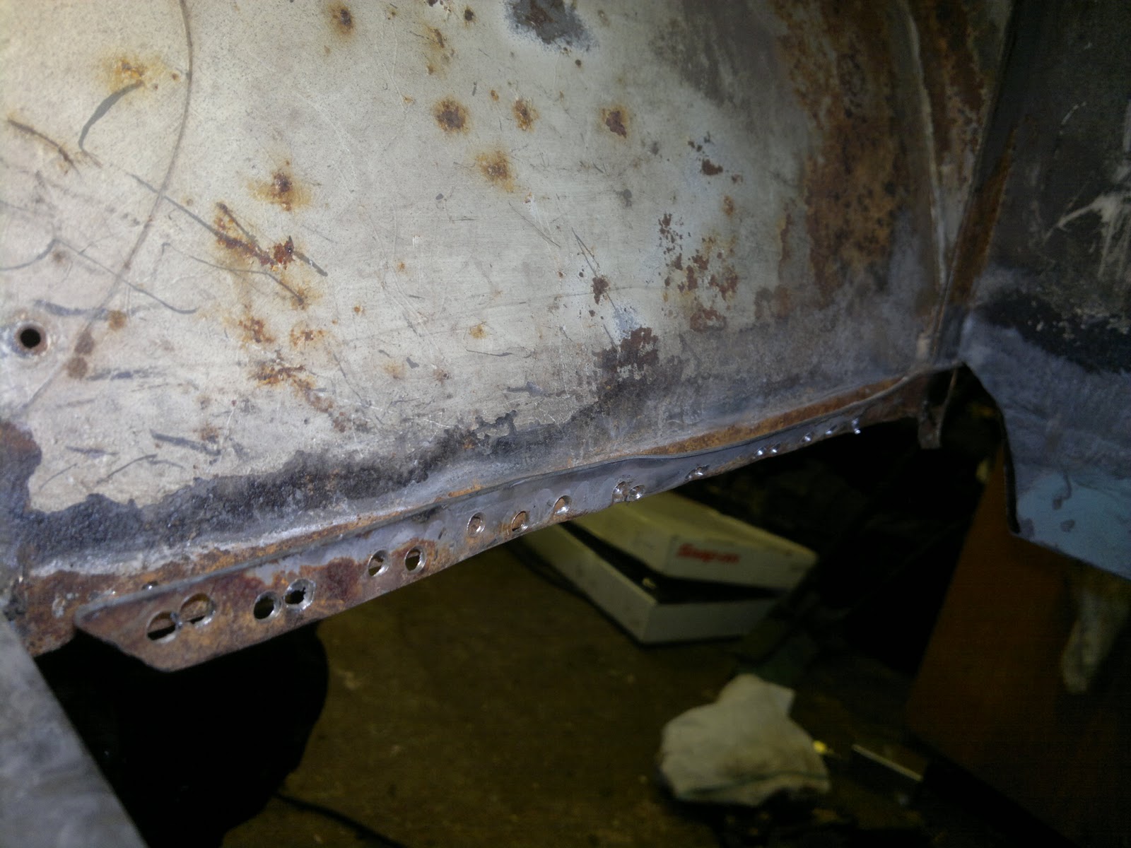
So with some delicate work with a drill I removed the spot welds on the splash panel and the battery tray lip that was fitted between the two, and tried to keep the wheel tub in as good condition as I could.
With the splash panel removed I stuck it in the sand blaster for a clean up, then welded up the spot weld holes. You may be able to see a strip of copper I used to stop the weld penetrating too far through the panel and also as a heat sink.
I replaced the corner that I left attached to the van when I ripped the panel out, using a piece I joggled and bent to fit.
A few hours' work and the splash panel is ready to fit back in.
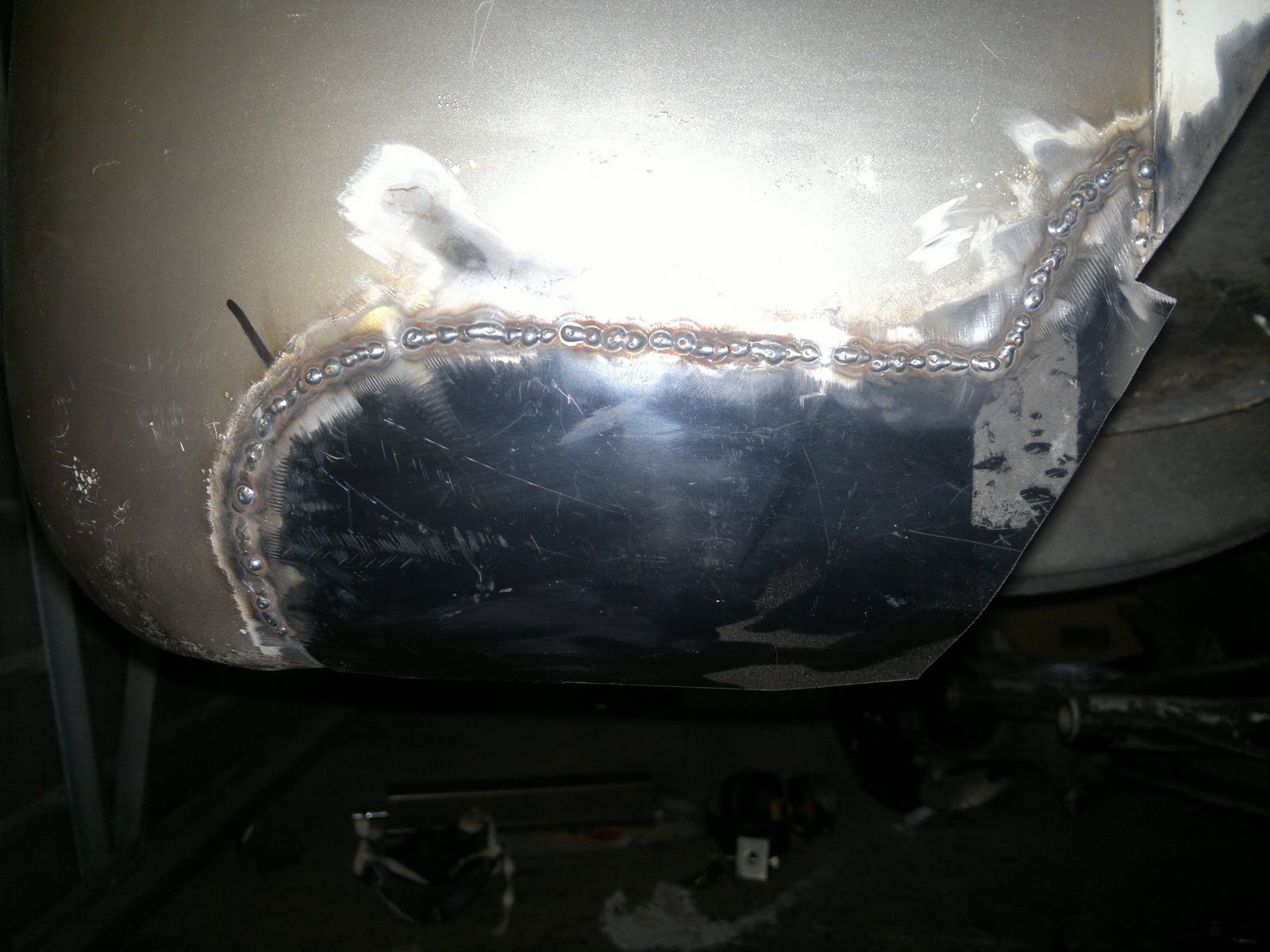
I then had the task of patching the double curved lower corner panel. This repair piece is cut from a cheap patch panel although it did not fit very well in its original shape I was able to position the panel to cut out a profile that closely matched what I needed for my repair patch.
A few tacks to ensure I kept the correct curve
I then very gingerly tacked the rest of the panel on. I ground off any welds that didn't penetrate enough and used a strong light behind the panel to find any gaps I'd missed once I had ground the welds flush. My method of taking it slowly to keep the panel from distorting was to only weld where the panel had cooled enough to touch, yes just like that bit in Men In Black. 
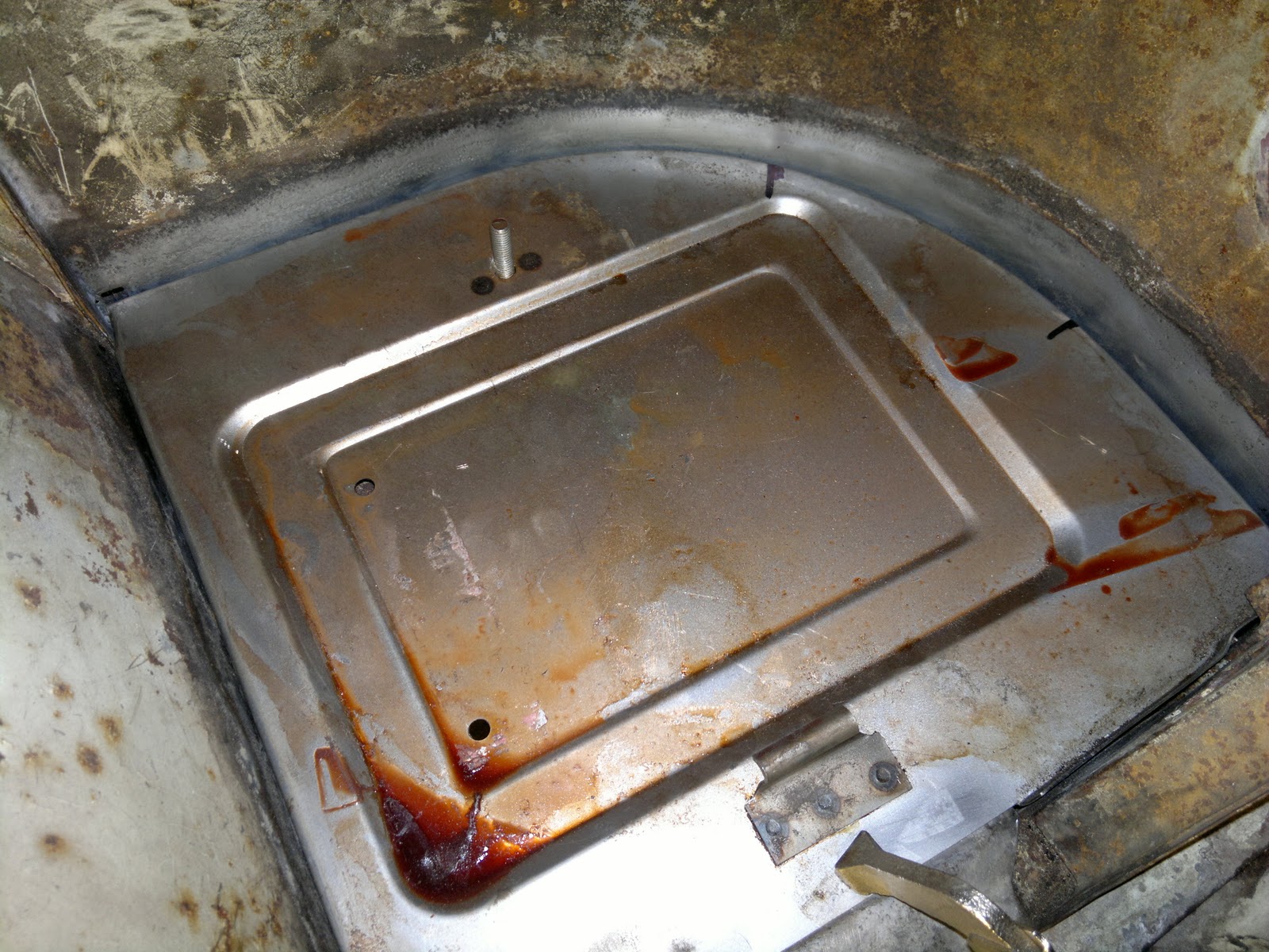
So a trial fit of the new battery tray panel from Creative Engineering didn't look too bad. The orange stuff on the panel is corrosion inhibitor not Hot Wing juice by the way. It can take me a while to get round to some jobs so best to keep the panels as fresh as possible.
The curved profile wasn't an exact match with about a 2-4 mm gap at either end, so I marked the contact points and beat the lip out on the edges and in on the crown of the curve, this didn't get it perfect but enough to get a better fit for panel beating later. 
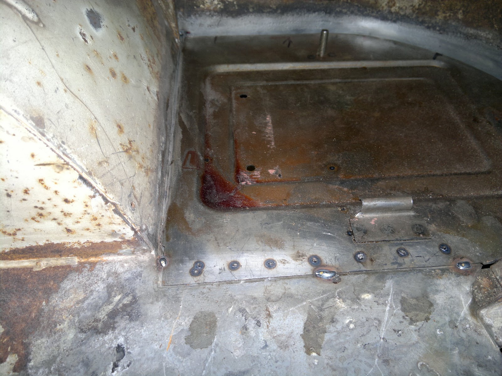
With a bit more messing around I finally got the panel in a position I was happy with. I used the joggled edge of the engine bay valance panel as my datum point for the corner of battery tray, (lower edge of picture) clamped the panel tight, then tacked the edge ready for a few spot welds.
I then attempted to slide the splash panel back up between the two panels and spot weld the three panels together. It went a bit wrong. I realise now that I'd painted the edge of the panel with weld through primer and this didn't work well with the spot welder. I managed to get a couple of strong spot welds but the rest of the panel was MiG welded at the edges and where I burnt through the panel with the spot welder.

Front beam chassis repair


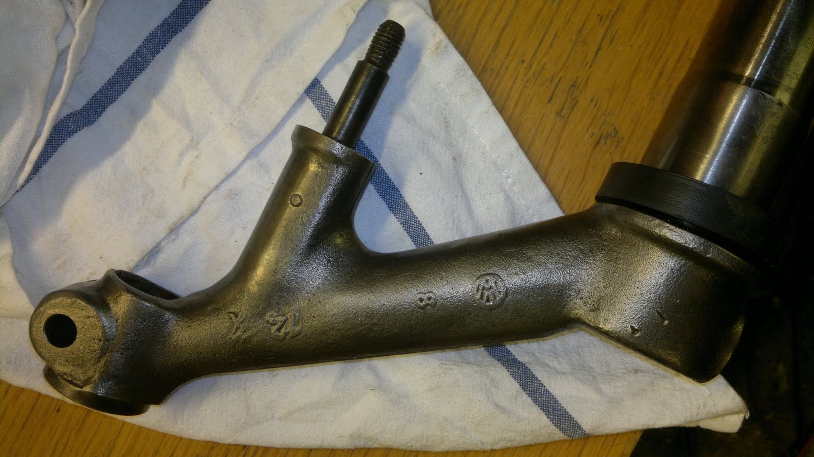
After taking the front beam off I ground out all the rust hiding under the beams upright. Here are a few pics of the repair patch.

Fitting Shocks to 4" Narrow Front Beam

I was able to have the privilege of using my Uncles old school belt driven lathe. It took me a couple of hours to get set up and remember how to use one of these from my apprenticeship days.
After 3 hours of messing about I finally produced these 12mm aluminium spacers. Trouble is they slid into the rubber bush more that I had measured for which sat the body of the shock just 2mm away from the upright of the beam.
I also calculated that the off set to the lower trailing arm mount to the the top mount is 35mm and I'd need to take the shoulder of the lower mount out by 12mm to keep the shock sitting vertically.
Or I could buy thinner Spax shock with swivel ends similar to what I have fitted to the back IRS.