Modifying Lower Trailing arm for 4" Narrowed Beam


I've had the dilemma if I should or how I could shorten the mounting position of the lower shock mount on the front beam lower trailling arms. I've scoured the internet for how to do it, without any luck so here's how I did it.

I could just cut the arm to the length I needed and drill out the existing bolt, but I first wanted to see if I could take the parts apart how they were assembled, and if that doesn't work then cut it up and drill it out. I started with the pin that holds the bolt in place.
Because the trailing arm is such an awkward shape to hold in a flat vice I came up with the idea to clamp the arm in a position between the drill bit and the tip of a bar (ground to a point, allen key pushed into a round lump of ali) using the positions that I centre punched on the pin.
This took a while to set up, I ended up using the cut off pieces of leaf springs from the front beam as spacers to clamp the arm, most importantly to keep the pin square to the drill bit. I first went through with a 3mm bit. this snapped as it tried to break through and left me with a broken bit inside the arm. Not easy to remove!
I then drilled as far as I could with a 4mm bit (the diameter of the pin) this then allowed me to knock the remaining part of the pin out with a punch.

Now onto pulling the bolt out. I first tried to pull it out cold but it didn't want to budge. so I then built myself a little oven at the end of the garden. Then donned my leather attire (I'm also a part time Gimp) and set about becoming a Pyro. I was able to draw the first bolt out with a steel spacer I made and a bunch of washers, this took about 4 attempts of heating the arm up for 3-4 min each time with a butane torch in a brick covered over/hamster house keep the heat local, this also helps saves gas and time.


As I was winding the nut down on the second bolt to draw it up through the spacer and washer under the nut it caught on the shoulder of the bolt, making me sheer the thread of the bolt.

This left the bolt half in the arm with no thread on the sticking out part to help draw it out.
To get around this problem I cut a new thread on the shaft, having first cut the arms of my die holder down so I could get the die to rotate a full 360 deg.
With the nut on the new thread, and a bunch of washers ready I was ready to try again. 
Another quick blast in the furnace and a lot of squealing as hot metal graunched on hot metal... like the droid torture chamber under Jabba's palace.
Finally both lower shock mount bolts came out, I made sure I left the arms to cool naturally so they retained their original material properties. If I had stuck them in a bucket of water to cool this would have hardened them but also made them very brittle.
Video of bolt removal after heating

So now with the pins out I can get on with modifying the trailing arms. I started by setting up the arm in the pillar drill using the existing 12mm hole and a drill bit to make sure its square. I then deepened the hole by what I thought was 12mm but ended up 18mm deep,  This means the depth of the hole now starts to go into the arm I hope it won't affect the strength.

So I then threaded the hole with a 14x1.5 mm tap using the tap in the drill at first to get me started to make sure it went in square, with the thread cut all the way down I then cut 13mm off the face.
I tidied up the burrs and mating face with a file.

I couldn't use the old shock mount bolts, as I broke one and they would no longer fit in the hole, so decided to make my own
They are 95mm steel rod with three steps 14mm, 12mm and 10mm, length to fit the arm, shock mount and nut. I'm just waiting for a 14mm die to turn up before I can fit the bolts/pins in the arms. I later found out my shock mount bushes are 12.5mm(1/2") holes so I my make another pair if there is too much rattle with the first batch!

So my 14mm x1.5 die arrives and I try to cut the thread in the lathe. This was tough so I tried turning a little more material off the outside diameter I finally managed to get the die to cut but by using the chuck key as a lever. This also caused the smooth face of the shock mount to score from twisting in the jaws.  
 I screwed in the new bolts in the trailing arms to check the depth of the 14 mm thread I'd cut, it got to the base with 1 mm sticking out but as I pulled it out with a couple of nuts twisted together on the 10mm thread end the bolt started to bind. This was not good.
After a lot of cussing, thinking I'd just scrapped a trailing arm and new home made bolt I tried winding the bolt out jammed in the vice, this lifted the bench off the ground. After shearing the new bolt and a couple of days break, scratching my head I finally managed to drill down the bolt with a 12mm bit, offset from centre close to the tip of the internal thread. This broke the bolt away and with the use of a punch in side holes I got the old bolt out in bits. whoop whoop. happy smily.

This let me to turn down my second set of bolts

 This time I started the thread cutting on the lathe with a little bit of taper on the end of the bolt and did the rest by hand. I used a v block and piece of tin plate to protect the shock mount face.

With the new bolt sliding into place I could check the fit with the shock. Not sure if the nut and washer should clamp the bush or allow it to spin?

A couple of pictures of the arms with the bolts


The final stage of assembly and the thread was thread locked with a low viscosity Locktite
 I then purchased a set of 120 roll pins from Halfords normally £8 but got then for £4 with a trade card. Anyone need 118 various roll pins?
 I drilled through the bolt first with a 3.2mm bit using the bit poked into the other side as a sight guide. Then opened this up with 5/32 bit starting from the opposite side.
 I picked a 4 mm (4.2 mm dia) roll pin and punched it through, using a centre punch on the end to flare the edges to help hold it in place.

 The other side was cut to lenth with a grinder as they are so hard and then both sides were cleaned up.

 There you have two lower trailing arms modified to fit a 4" narrowed beam
The arms were then sent for powder coating, a clean up around the edges and there ready to fit.


Rear shock mounting for 944 IRS conversion pt5

This will be my fourth attempt at welding these supports so I should be able to get it right by now. I folded up the piece needed to provide the space for the clearance of the shock when it swings forward and backwards.I used the bench to make sure the two pieces were straight with each other. So as I welded the two parts together I set the bench alight, and didn't notice until I couldn't see the weld through the smoke and had to lift up my welding mask.

With the clearance piece welded in and a few more trial fits I then reamed the shock mount holes with an adjustable reamer and used one of the bushes as a guide. This didn't really work as well as I hoped. The reamer wobbled because it was such a large diameter for using by hand and this caused it to cut a jagged hole. I should have put it in a pillar drill. The hole still came out with a snug fit for the bushes just not as clean as I had hoped.

A few more trial fits and I was able to mark where the swing arm wanted to foul the edge of the support. The clearance issue was sorted using a huge mallet, steel dolly and some old decking that used to cover up the fish pond. Yup, just like Thor.

This time I tried to bend the radius where the two parts met before it was welded in place. but I ended up bending the two edges at different heights and still needed to place a couple of cuts to relieve the bends. I later dressed (hit with a large mallet) the ends so they aligned once the support was welded in place

A picture before assemble because I got a bit snap happy with the camera.

This is the support painted, assembled and checked for the shock clearance at the correct height for the top shock mount hole and the supports squareness with the other side.

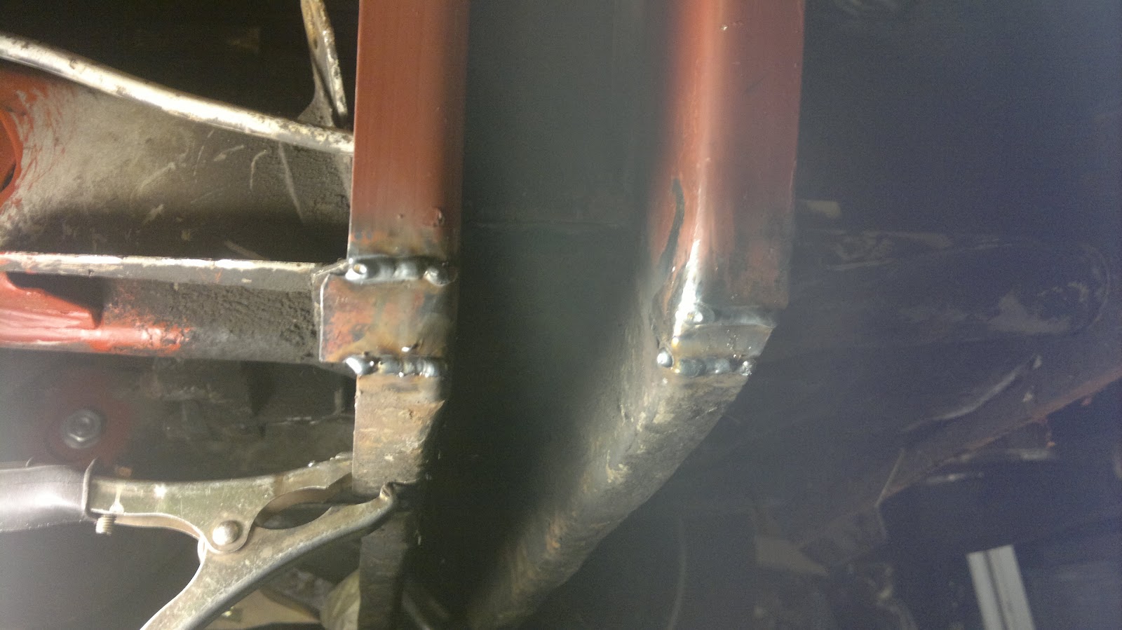
The A arm and shock was then removed and the support welded into place with a seam weld either side at the top and a seam weld inside and out at the bottom but finished flush to try and make it look like I'm good at welding. I may add another weld inside at the top as the skin it's welded to is thinner on the inside of the chassis than the outer where the original mount was welded. I have seen a shock mount  welded on the inside rip away from the chassis, so I will have to consider this.

I had one last bush to trim to size, so I used my new toy which took 5 minutes..

I could try and sort out an anti roll bar but I'll recondition the hand brake shoes first, sort the hand brake cable out, work out what length drive shafts I'll need and see if the wheels are straight and square with each other first.

Heres the parts I've made or had made to get this lot to all fit together.
With a couple of used tyres slung on the wheels the van is finally on the ground with its new rear end. This has taken a lot of work, too much time, mental skills and help from a few friends but is now finished (nearly), so up yours to who ever told me it could not be done.

Rear Shock Mounting for 944 IRS conversion Pt4

With the left shock mount welded in place I just needed to tidy up the excess material from the new section sticking out the bottom.
I sorted this out by cutting a bending block to the radius I wanted clamped it to the van then started hitting very hard with a really big hammer, this didn't quite work as I had hoped.
So I had to make a couple of strategic cuts with the angle grinder then start hitting it again really hard.
With the help of the gas torch I finally managed the bend I needed

Then welded up the gaps
Ground the welds down then hid the welding with some red oxide paint

With one side done I get to start on the other side.
With a little less disregard than the first time I cut the van up. I dug out the electric saw I had for cutting my hedge down, It took me 2 min to pull the support out.
Then cleaned up the surface of the spot welds so I could see where to drill them off.
With the old support out the way I can mark the cutting angles I need.
to be continued.......

Converting the Garage to a Workshop

I've had the pleasure of becoming the proud owner of a 1950 lathe, a pillar drill and a small milling machine.

The trouble is where to put them, the garden shed is full of rubbish, Rachel said its a no go for the dining room, so I guess I'll have to re arrange the garage. 

With the van wrapped up and moved out of the way on a shopping trolley. Rachel (after possibly feeling bad for not letting me take over the house), said she would help so I was able to persuade her to clear the painted part of the garage floor ready for the new arrivals. 


With some help from a couple of friends and a hire van we hauled the equipment in to its new home.

With an early start the next day I locked the dog out of the garage (she'll only turn some wooden chair legs on the lathe if she's not watched closely)  and started painting the centre of the floor on probably the coldest day we have had in 2012. This meant the paint was like treacle.

By the end of the day when I wanted to move the van back in the paint was still wet, not wanting to leave the van out I pushed the van back in on its shopping trolley, wheels wandering all over the place leaving behind a trail of fresh paint tracks and blue tyre tread. 


It finally took 3 days for the floor to dry before I could walk on it without sticking to it like a Scout Hut carpet and go and play with my new toys. 
p.s. the dog did manage to sneak in and leave a paw print on the new floor but I managed to catch her before she made a set of chair legs . 


Rear Shock Mount fitting for 944 IRS conversion Pt 3


I was able to visits my uncles workshop and turn down a couple of brass bushes to fit inside the top mount bearing this is because the bolts I'm using is 12mm and the bearing hole is 15mm. I also found out later I used the wrong cutting bit. that's a whole different world.
I also faced of one of the other bushes to give me the offset position I needed for the top mount. when at full extension the shock is vertical and the top mount collar just sits off the forward face, when compressed the shock swings back and because of the off set now sits clear of the back face.
Now that I'm happy with the top and bottom shock mounts I cat fit the new section. I removed the spring plate and A arm then clamped the lower part of the section with panel clamps and adjusted the top till it sat square with a bit of persuasion and also lined up with my previous marking of the highest and lowest position for the mount bolt.


With the upside down, on my back, stuck under the van, not able to move welding done and the spring plate and A arm fitted you can now see the final result.


I'll tidy the lower point and form a radius and then there's just the other side to do, just hope it does not take me 6 month's.