944 IRS conversion

Taking a break from all the welding and body work, I managed to drag my mate Tim from working on his own van to spend the day removing my rear end and measuring up for the sexier back side. On the VW not my own body. He's not an amateur surgeon. Just to clear that up... This is a Porsche 924s (not a 944 as stated in the title but I think they are the same) rear axle that I ordered from Porsche Apart and it arrived in a box as wide as my garage, doing a little VW to Porsche IRS conversion research online I've found that there are two types of 944 aluminium A arms, one shorter than the other, I hope I have the right one. I've also had a few comments that this can't be done so lets see if they're right.

I've played with the hubs and discs previously (usually when I'm alone in the house) but it was now time to get the serious stuff sorted out. So a quick spray of penetrating oil on all the bolts and the original gearbox and reduction boxes pop out after 40 years with no bother.
Here are the A arm mounting points on the 924s beam, this beam is the same diameter as the bus one at 90mm. I may try and use these mounts if I can't work out how to make a fresh pair.
The mornings' work gave us the measurements we needed to calculate the size and shape of the A arm and most importantly if they would fit. I've drawn up a plan of the measurements to get an idea of how things are going to fit (the arm on the drawing is a bit fat). The Porsche axle wheel offset including discs worked out to be 1497mm across, the Bus axle with the original reduction boxes and drums came up as 1445mm across. To keep the outer wheel rim in the original position under the arch and using wheels with an extra 40mm offset means I'll need to locate the A arm mounting points 46mm closer to the center line.
I've also stolen a couple of photos from the SSVC 'For Sale' forum of a 944 rear end and edited them to show the comparison of the different length arms below. Please don't sue me if you hold the copyright of these pics. The longer arms have no bump stop molded in the arm and a longer reach from the spring plate mount.
Before we removed the spring plates I marked their position across the spline shaft with a junior hacksaw then carefully slid them off making sure the inner portion of the splines stayed in position, if the moved I'd have to waste a lot of time later setting the ride height to the correct set up. The 924 spring plates are a lot shorter and made of two plates, the outer plate has the inner spline tube poking out (the spline is smaller than the VW one) the tube is slid through the inner plate and held in place by the two bolts one is elliptical used for adjusting the ride height, the plates are sandwiched by rubber bushes and bolted on in the same way as VW do it. With the reduction gear boxes out the way we decided to see what sort of ride height would look good. These are 205/60/15 unfortunately they are touching the top of inner arches. But you must admit it does look good! (No the grass isn't real, I R Photoshop King)

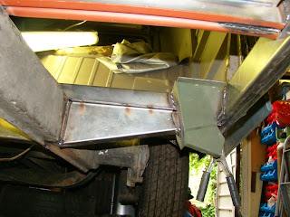
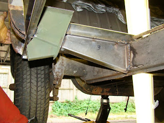
Fitting outriggers and jacking points

I've finally started to see some progress with the endless task of repairing the cargo bay chassis. With a bit of cutting, measuring and banging with a huge mallet I was able to fit and weld the outriggers I'd made with the new jacking points I definately did not make. I thought I'd made some real progress with my welding until I started doing it against the laws of gravity. Guess I've still got a few things to learn!
A few tack welds hold the outriggers in place untill I can get my hands on a spot welder.This is the right side fitted. I levelled and positioned it with a spirit level clamped across the beams like the Professional I deep down am. (Yes in the picture the spirit level is actually invisible)
Although I still needed to spot or mig weld the forward support section to the bulk head so I can fit the front outriggers and centre cross member, I couldn't help trial fitting my new cargo floor before I got called in for tea. No I don't still live at mums but I did eat fish fingers and beans.

Re fitting cargo floor chassis rails Pt 2

Once both sills were fitted I cut the chassis rails out any way I could, trouble is I needed the tubes embedded within the rails. With a tiny 1mm cutting disc I delicately cut them free from the welded frame brackets.

I also removed the brackets from the centre of the I beams that securely hold the gear link tube in position. To do this I again unleashed the 1mm cutting disc very carefully and gingerly (see what I did there?) using plenty of light to see what I was doing cut away the weld, wobbling the I beam regularly to break the weld. Once each rail was slid off the tube I drilled the 8 spot welds off each side.

With the main chassis rails cleaned I placed all the cross members in their positions and using the datum marks and laser I marked out the centre and handbrake cable tube holes. When I hastily cut and folded all these parts originally I didn't order enough material to fold all three top hat sections, so the other two I picked up from the Autocraft engineering stall at Van Fest, the quality of these parts is spot on, and surprisingly fitted perfectly between my new fitted sills.
I had originally decided to manufacture many of my own parts and save money, this was decided before I knew what parts if any were available, or the quality of the ones that I could buy, and also because of my previous crap panels I'd bought before. This meant I created for myself a few problems- marking and cutting a 31mm tube hole without a pillar drill accurately in bent 2mm and 4mm sheet is not easy, requires patents and can be very time consuming, the only tool I thought was available for a pistol drill was a tapered drill bit. Backed up by wood I started drilling slowly, straight away skidding off my markings, then unable to control the awesome speed of the cutter I burnt out the drill and hardened the sheet steel, like an apprentice fitter I once was. All this trauma and it was still my first hole! I was having a bad day, it felt like I was wasting precious garage time on these parts that I'd made and I was getting really grumpy. I decided I would bit the bullet and order all the chassis parts I needed. The prices online came to over £200, again I changed my mind and decided that my local machine shop would save me, and do the drilling for me at £10 a hole (over £40 total). They sent me away with the advice to try an electricians' hole saw and come back if I had no success, or produced yet more warped glowing red sheet steel. With a good lunch and large bottle of Coke (other brands of pop are available) inside me and my new tool in hand I tried one more time. I was surprised how tough and accurate the hole saw cuts were but I do need to ask Santa for a pillar drill (if you're in New Zealand it's pronounced Sinta by the way). It's all about using the right tool for the job. Or buying one.

Refitting cargo floor transfer cassis rails

Having been away from the garage again for another few months, I finally managed to find the time to continue putting the van back together. With all the old cargo floor cross supports cut out of the way, I just needed to grind away the remaining metal from the front cross member I left spot welded to the lower part of the forward bulkhead. This took all day to carefully grind the spots off the thicker steel of the cross member without damaging or ripping the thinner front bulkhead lower skin. Getting a bit impatient I did chisel a couple off, making holes I'd need to tidy up later.
With all the chassis cross members and transverse chassis rails removed I then ground away all the welds on the heater, clutch and accelerator cable tubes where they had been attached to the cross rails, then cleared the rust from where the new rails are going to sit.
Starting with the I beams or "transfer chassis rails", I paired up the C shaped sections I'd bent earlier from 2mm sheet steel, I then folded the ends using a block and mallet to fit correctly between the sills, clamped together I then trial fitted them onto the chassis using the earlier markings, making sure the tops were flat, square and level for where the floor would sit.
With the chassis rails all lined up I then seam welded in a few places along the top and bottom. They are now ready to mark out and drill to fit the hand brake cable and gear shift tubes, before final assembly to the chassis.

cutting cargo floor cross supports

Here are a few photos of the cargo floor chassis being removed, I'll add a better description when I get more time.

Just like Austin Powers, yes that is a frickin' laser !

Right Inner Sill Repair

With the left side cargo door sills now in place it was time to turn the van around so I could access to work on the other side. The inner and outer sill on the right side have seen repair panels before, the skin panel was a repair panel I cut off along time ago when the van was first taken off the road (over 10 years ago) and the patch work of galvanised sheet metal shelving and filler I'm ashamed to say was my first attempt of van restoration may moons ago. hopefully my quality of work has moved on.
The steel at the back of the inner front arch is a popular rot spot, despite my earlier efforts I cut away the many layers of panels holding this corner together. This is a lot easier with the wheel arch removed but again forming all these panels by hand eats away any precious garage time. I had to joggle the flat patch panel again(see previous blog entry) and to form the bottom of the B pillar correctly I needed to cut a hard wood bend block with the curve shaped from the other pillars. I then used a blow torch to soften the steel allowing me to shrink the sheet while forming the curve around the block. This really helped get the contour of the bottom of the B pillar correct.
As you can see the rear arch inner where the sill attaches needed a smaller patch than the mess at the front. The cross struts for the floor were left in place to ensure the inner sill was clamped in the correct position. The new sill that Id previously folded from a thicker gauge steel just needed the ends bent up to fit the length. With the front and rear arches repaired I aligned and leveled the sill; tacked; checked and welded it into place. I now have to decide If i should fit the outer skin before or after I've finished the cargo floor.

Crago Door Sill Repair

With the door gap braced along its' length with a piece of angle iron I cut away the original outer and an old repaired inner sill. I then welded the strengthener sill to the outer sill that I got from Auto Craft, cleaned up any welds and trimmed any excess metal from the van and the panels that prevented a comfortable fit for all the parts.
Trying to get the sill aligned just right to the doors, current chassis and curve of the body took a lot of trial and error until I was happy with a position I liked. Although this meant the rear wheel arch patch I'd fitted earlier didn't match at the lower lip and had to be reworked to align. The outer sill was then tack welded, checked for alignment with the door gaps, their closed position and the outer curve of the van, and then finally the sill was welded in position. I worked out from the old floor that the top of the outer sill sits about 8 mm higher than the top of the chassis rails because of the step in the floor panel.
When fitting the inner sill I had to pull the sill into the center with rope (!) to get the outside bodyline straight and to reduce the gap between the sill and the chassis rails. Although I supported it with the angle iron it still bowed out at the rear cargo door hinge line. Unfortunately at the moment I'm not welding the inner sill to the current chassis as these pieces will be replaced later, so with the inner sill positioned correctly and just welded at either end I have to sort the gaps to the chassis again later.

Manufacturing Chassis Supports


Although I haven't been in the garage for a while, I have been able to get into the workshop and fold up a few more parts for the cargo floor chassis. The hardest part of hand forming is getting two parts the same. If your first fold is a little off it can become a big error on the last fold.


I had to cut away the tab that should run along the full length of the top hat section because I would not have been able to fit it into the folding machines jaws. But that's not too bad as this is where the jacking points will be. The others tabs I will fold up when I get the parts to the garage so that I can make sure the fit is correct.


Here's the drawings I made.

A is the I beam
B is the top hat sections
C is the inner sill
D shows the angle for the aft cross section to account for the chassis rails widening.
E is the capping plate for the rear cross section because it has no other pieces below it.


The outrigger I mad a paper template from the measurements taken from the hole left and used this to get the angle of the fold correct.


Chassis Patch Repair

With the extra piece of steel the metal supplier gave me I was able to neatly patch the hole in the left chassis rail.
It's great to be able to weld decent gauge steel without having to worry about distorting it.